190-02246-10 GI 275 Part 23 AML STC Installation Manual
Rev. 11 Page 4-17
Notes:
[1] Screws can be substituted with any suitable pan head or countersink #8-32 UNC-2A
aerospace steel screws.
[2] Torque screws to 8.0 ± 1.0 in-lbf.
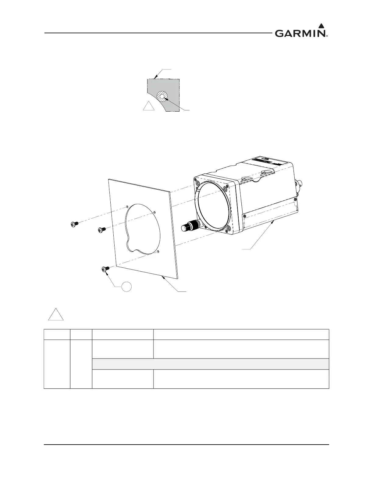
Figure 4-11 Installation of GI 275 Display in the Instrument Panel
THE AREA ON THE BACK OF THE INSTRUMENT PANEL THAT COMES IN DIRECT CONTACT WITH THE GI 275
MUST BE PREPARED FOR ELECTRICAL BOND PER SECTION 4.3.2. PREPARE AREA 0.125 INCHES LARGER
THAN THE GI 275 METAL INSERTS.
ITEM QTY PART NUMBER DESCRIPTION
1 3
MS35214-XX
[1] [2]
SCREW, MACHINE, PAN HEAD, CROSS-RECESSED,
BRASS 0.164-32 UNC-24
OR
MS24693BB-XX
[1] [2]
SCREW, MACHINE, FLAT COUNTERSUNK HEAD, 100°,
CROSS-RECESSED, BRASS, #8-32 UNC-2A
1
INSTRUMENT PANEL
REF
GI 275 REF
INSTRUMENT
PANEL
GI 275FASTENER
HOLE3 PLACES
%$&.2),167580(173$1(/35(3$5$7,21
,167$//$7,21,1,167580(173$1(/

 Loading...


