190-02246-10 GI 275 Part 23 AML STC Installation Manual
Rev. 11 Page 4-67
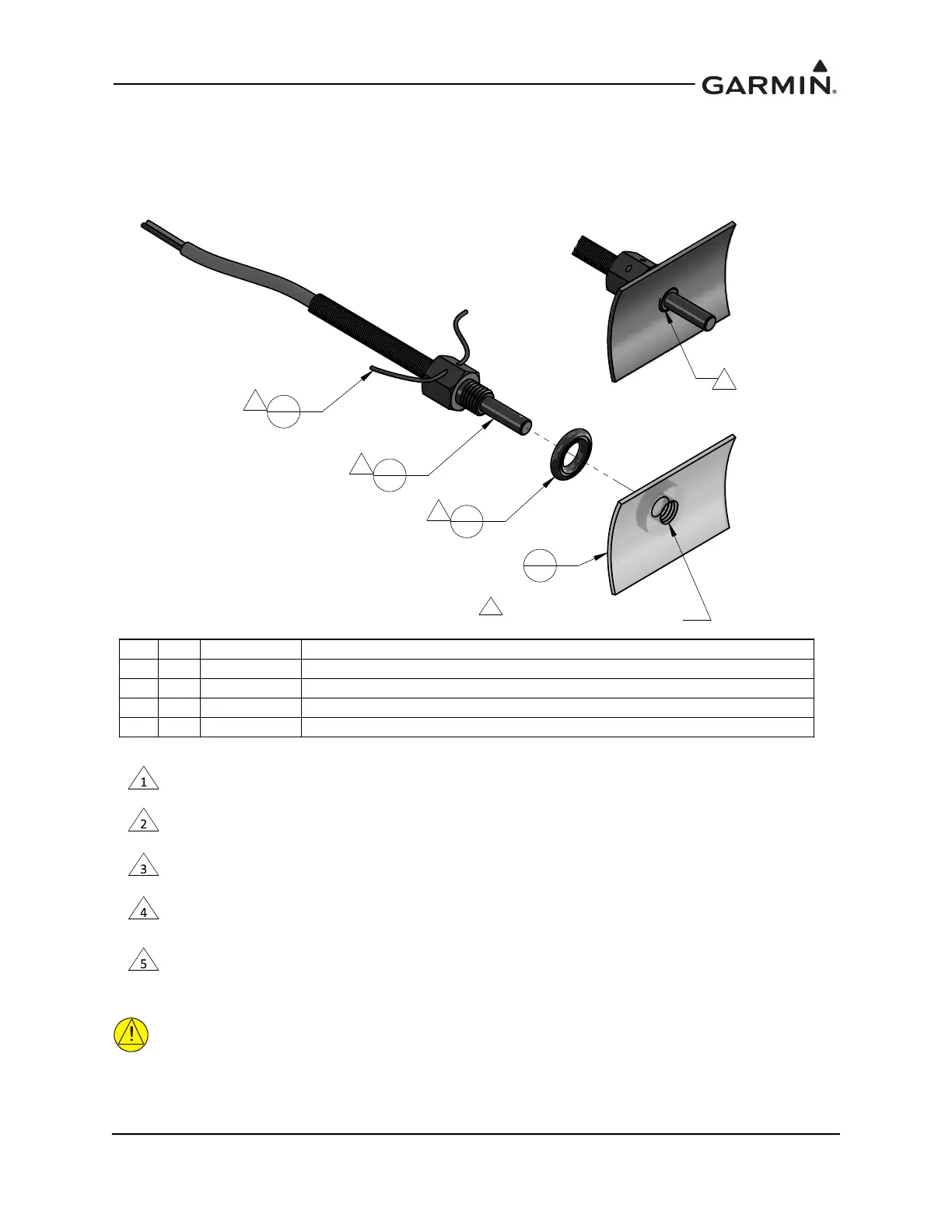
4.7.3 Carburetor Air Temperature
The sensor location will vary for different carburetors. This STC provides the basis for airworthiness
approval only for the temperature sensor installed in the existing port with 0.2500-28UNF-2A thread.
Refer to the engine or carburetor manufacturer data for temperature sensor location, if required.
Figure 4-49 Carburetor Temperature Sensor Installation Example
CAUTION
Fuel and air passages must remain free of contaminants during work near and around the
carburetor.
1
1
2
1
3
1
4
1
5
REF. EXISTING 0.2500-28UNF-2A
THREADED PORT IN CARBURETOR WALL
2
3
4
1
NOTES
QTY
ITEM
PART NUMBER
DESCRIPTION
14
CARBURETOR, EXISTING
13
MS35769-2
GASKET, METALLIC, ENCASED, ANNULAR, COPPER, Ø1/4 ID×Ø1/2 OD
12
MS20995
WIRE, SAFETY OR LOCK
11
T3B10-SG
PROBE, CARBURETOR TEMPERATURE
WHEN INSTALLED, FACE OF THE SENSOR THREADED BOSS IS FLUSH WITH THE INSIDE OF CARBURETOR BARREL. USE
WASHER(S) IF REQUIRED TO SPACE THE SENSOR ACCORDINGLY.
T3B10-SG TEMPERATURE SENSOR HAS 0.2500-28UNF-2A THREAD. INSTALL WITH MEDIUM STRENGTH THREADLOCKER.
EXERCISE CAUTION TO PREVENT FUEL CONTAMINATION.
SPLIT FACE OF THE GASKET FACES NON-ROTATING SURFACE.
SAFETY WIRE PROBE IN ACCORDANCE WITH SECTION 7, SAFETYING OF CHAPTER 7, AIRCRAFT HARDWARE, CONTROL
CABLES AND TURNBUCKLES OF AC43-13-1B, AIRCRAFT INSPECTION AND REPAIR.
SENSOR INSTALLATION IN EXISTING CARBURETOR PORT ONLY. ADDITION OF NEW TAPPED HOLES TO CARBURETOR
BARREL NOT ALLOWED.

 Loading...


