190-02246-10 GI 275 Part 23 AML STC Installation Manual
Rev. 11 Page 3-8
Circuit breakers and switches added as part of GI 275 system installation must be labeled as shown in
Table 3-9 (switch), Table 3-10 (single bus), and Table 3-11 (independent buses). Labels must be readable in
all lighting conditions. Ambient flood lighting is acceptable. The labeling for each LRU denotes the
following where applicable:
• Number designation – LRUs of same type/function in the system.
• A/B designation – Differentiates the essential bus
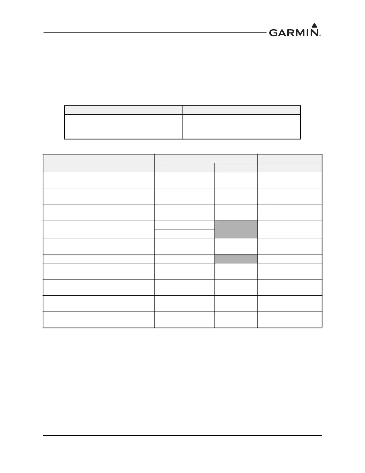
Table 3-9 Switch Labels
Table 3-10 Circuit Breaker Labels - Single Essential Bus
Notes:
[1] Label as “STBY ADI” if the GI 275 is configured as a Standby ADI and no MFD pages are
configured.
[2] Label as “MFD/STBY ADI” if the GI 275 is configured as an MFD/Standby ADI and MFD
pages are configured.
[3] Not connected to essential bus. Refer to Table 3-8.
[4] It is acceptable to use a fuse in lieu of a circuit breaker for the GSB 15.
[5] If a GSB 15 Type-C unit (P/Ns 011-04937-20, -30, -40, -50) is installed in a 14V electrical
system, a 7.5A breaker or fuse is required.
Description Label
Display backup switch
DISPLAY BACKUP
Position 1: ON
Position 2: AUTO
Description
Label CB Value
Single LRU Dual LRU 14V / 28V System
GI 275 configured as Primary Attitude
only indicator (Basic)
ATT
ATT 1
ATT 2
5A
GI 275 configured as ADI
(3-in-1 or 4-in-1)
PFD
PFD 1
PFD 2
5A
GI 275 configured as MFD MFD [3]
MFD 1 [3]
MFD 2 [3]
5A
GI 275 configured as MFD/Standby ADI
STBY ADI [1]
5A
MFD/STBY ADI [2]
GI 275 configured as HSI HSI [3]
HSI 1 [3]
HSI 2 [3]
5A
GI 275 configured as HSI/Standby ADI HSI/STBY ADI
5A
GI 275 configured as EIS EIS
EIS 1
EIS 2
5A
GEA 110 ENG SNSR
ENG SNSR L
ENG SNSR R
5A
GEA 24 ENG SNSR
ENG SNSR L
ENG SNSR R
5A
GSB 15 USB
USB 1
USB 2
5A or 7.5A [4] [5]

 Loading...


