190-02246-10 GI 275 Part 23 AML STC Installation Manual
Rev. 11 Page 4-57
4.6.3 Backup GPS Antenna
The backup GPS antenna is designed for installation on top of an existing instrument panel glareshield.
The selected location must offer good visibility of the sky through the windshield.
Installation of the backup GPS antenna is optional. When installed, the antenna cannot obstruct or limit the
pilot’s vision (even though the antenna has a low profile). The optimal antenna position is horizontal or as
close to horizontal as practical given the shape of the glareshield.
Fastener holes for non-removable antenna installation, as depicted in Figure 4-41, must not penetrate
through the ventilation or defrost channels built into the glareshield, if present. If the glareshield is part of
the instrument panel structure, fastener holes may only be drilled if allowed by the aircraft maintenance
manual or structural repair manual.
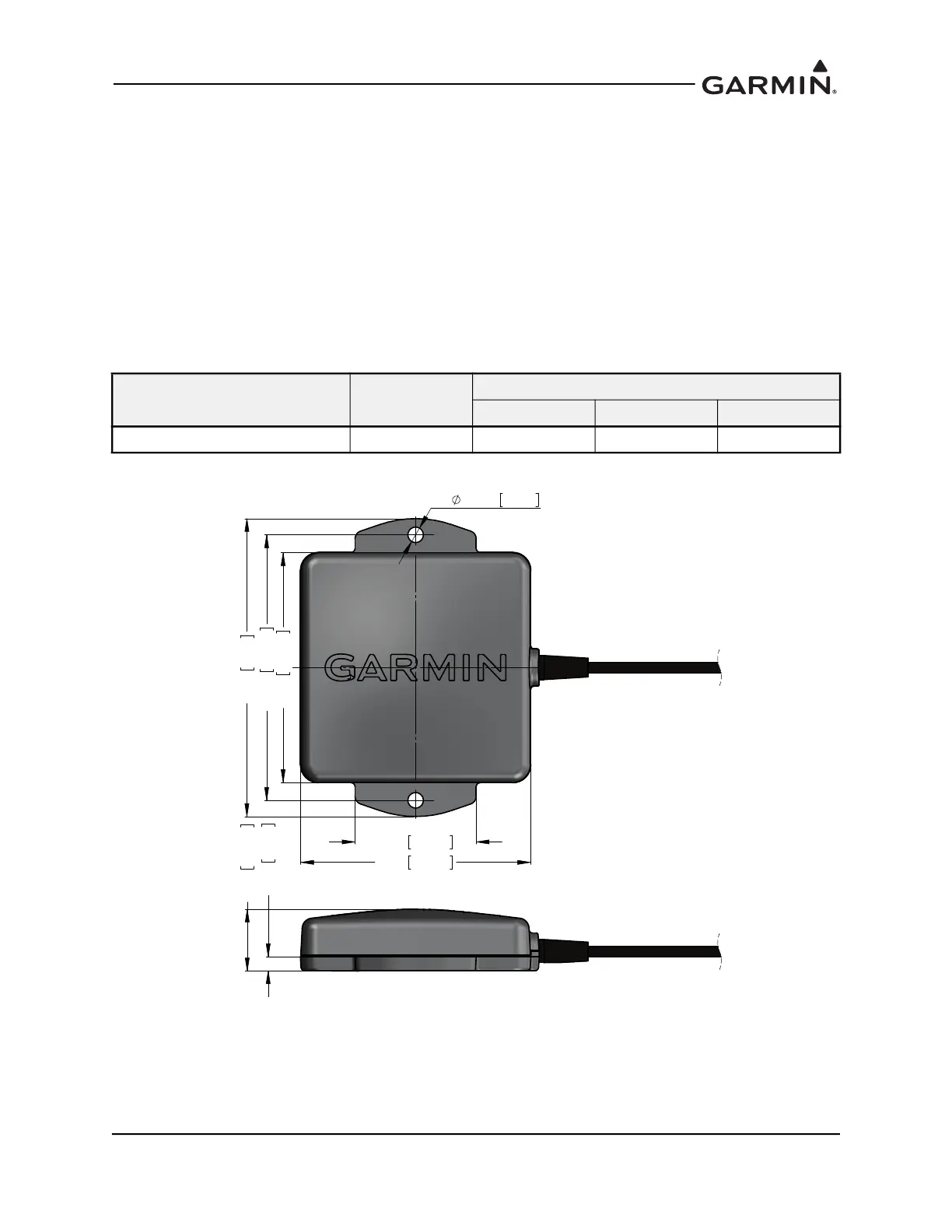
Table 4-9 Backup GPS Antenna Weight and Size
Figure 4-40 Backup GPS Antenna Dimensions
Item
Weight
lb. (kg)
Dimensions in. (mm)
Height Width Depth
Backup GPS Antenna 0.20 (0.092) 0.60 (15.2) 2.88 (73.2) 2.22 (56.4)
LQ
PP
LQ
PP
LQ
PP
LQ
PP
;
LQ
PP
LQ
PP
LQ
PP
LQ
PP

 Loading...


