- 56 -
Retro
RetroRetro
Retrofitting NiTRO
fitting NiTROfitting NiTRO
fitting NiTRO
900 and
900 and 900 and
900 and 1
11
1000 to NiTRO
000 to NiTRO000 to NiTRO
000 to NiTRO
400
400 400
400 and NiTRO
and NiTROand NiTRO
and NiTRO-
--
-X
XX
X
400
400 400
400
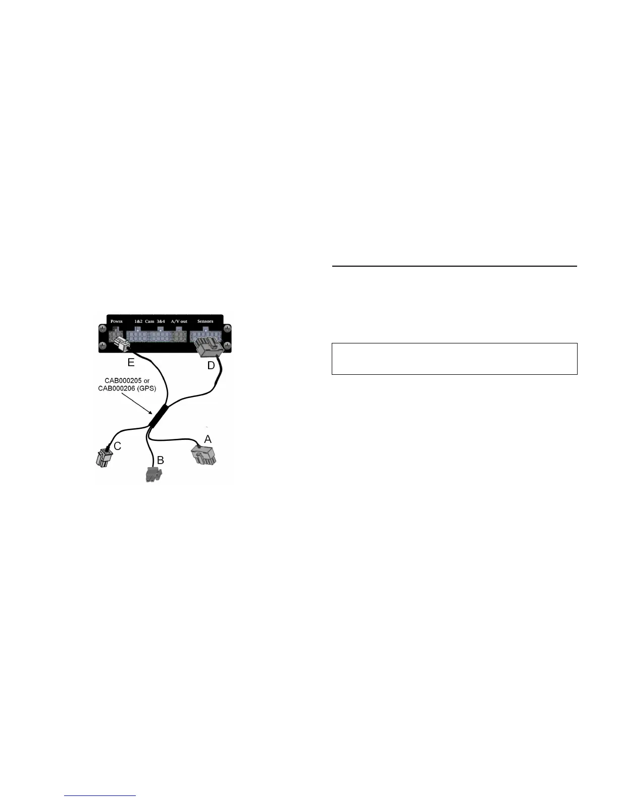
When utilizing the existing power / sensor cabling of either a NiTRO 900 or NiTRO 1000
an adapter cable, CAB000205 or CAB000206 (GPS) is required.
Please
Please Please
Please Note
NoteNote
Note that if the new system to be installed is a NiTRO-X 400 system an additional
power adapter cable, CAB000268, will be required. CAB000268 takes the 4 pin connector
(E) and changes it to the required 6 pin power-in connector.
A: 14 Pin Female Connector. Connects to installed sensor cable.
B: 2 Pin Power Connector. Connects to installed main power cable.
C: 4 Pin Male Connector. Connects to installed GPS module (Only applicable on CAB000206).
D: 14 Pin Male Connector. Connects to the Sensor input on the rear of the NiTRO or NiTRO-
X DVR.
E: 4 Pin Male Connector. Connects to the Power input of the NiTRO DVR.
- 13 -
Figure 1 Definitions
Figure 1 DefinitionsFigure 1 Definitions
Figure 1 Definitions.
ITEM #
ITEM #ITEM #
ITEM #
DESCRIPTION
DESCRIPTIONDESCRIPTION
DESCRIPTION
PART NUMBER
PART NUMBERPART NUMBER
PART NUMBER
1 N40x SENSOR CABLE CAB000218
2 VIDEO OUT CABLE GSX-N400X/VIDEO/AUDIO-OUT ASSY
3 GPS MODULE W/15’ CABLE DVRGPSN40X_ASSY
4 CAMERA CABLE 15’, 30’ or 60’ CAB000142
5 N40x VIDEO ADAPTER CABLE
SINGLE-CHANNEL
CAB000209
6 N40x VIDEO ADAPTER CABLE
DUAL CHANNEL
CAB000202
7
NITRO POWER IGN CABLE WITH 4
PIN CONNECTOR
CAB000219
(4 PIN)
7
NITRO-X POWER IGN CABLE
WITH 6 PIN CONNECTOR
CAB000262
(6 PIN)
Connections.
Connections.Connections.
Connections.
•
Constant 12 volt power must be provided to the NiTRO™ or
NITRO-X
. The preferred
connection is at the main bus battery(s), with an alternate connection source at the 12v
terminal in the electrical panel which is supplied power from the battery with a 4 gauge
wire or thicker.
•
This source must maintain a minimum of 8v during engine cranking.
•
The 12V+ side of the constant power connection (CAB000219/CAB000262) must be
fused at the power source with the fuse provided.
•
If main harness extension is required, use only 16 AWG or thicker wire.
•
Main ground needs to be connected to a solid chassis ground, preferably the negative
post at the battery, if not possible ground in the electrical panel, a shake-proof or lock
washer is required in the head of the bolt. Scrape away any paint to ensure a clean
connection.
• Connect ground to a clean, independent source
• Route CAB000218 harness to the electrical panel and route the “ALARM/LED”
harness to the drivers switch panel ((where the alarm button will be mounted) See Figure
2 for more information).
• Connect ignition sensor wire (WHITE wire from CAB000219 (4PIN NiTRO)
CAB000262 (6PIN NiTRO-X) to a switched/accessory 12V source (confirm that you
are not connected to the Noise circuit) e.g. switched side of body solenoid.
• Confirm camera configuration and route camera harness(s) (GSWHC2-15, GSWHC2-
30, GSWHC2-60) to desired location (make note of lens size and cable length)