- 8 -
Record on a separate sheet the Bus ID along with the Serial Number of the NiTRO™ or
NiTRO-X Control Unit and the SD Card for each bus for future reference. Ensure all system
components are accounted for prior to installation. Contact Gatekeeper Systems, Inc. if any
components are missing or if they appear defective.
Product Overview
Product OverviewProduct Overview
Product Overview: NiTRO
: NiTRO: NiTRO
: NiTRO
400 Series
400 Series 400 Series
400 Series.
..
.
NiTRO
NiTRONiTRO
NiTRO
401 (
401 ( 401 (
401 (DVRIDVMDR-401AV)
))
) :
: :
: NiTRO
NiTRONiTRO
NiTRO
404
404 404
404 (
( (
(DVRIDVMDR-404AV)
))
)
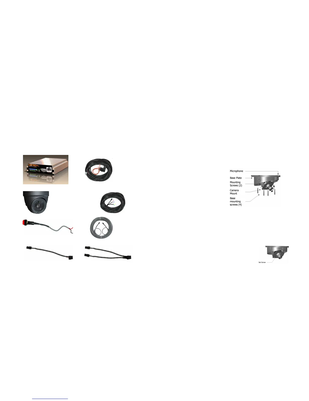
NiTRO400 Series
NiTRO Power Harness.
(P/N: CAB000219 (4pin) 30’ )
S-Series Camera
Sensor Harness CAB000218
Alarm Button (SMARTFLAG)
Camera Harness(GSWHC2N-XX)
Available in 15’; 30’ and 60’ lengths
Camera Adapter Harness (CAB000209)
Camera Adapter Harness (CAB000202)
- 61 -
Ceiling Mount.
Ceiling Mount.Ceiling Mount.
Ceiling Mount.
Connect camera harness input to camera.
Tuck attached camera harness behind the camera circuitry and then mount base to the
ceiling with the four screws supplied.
Focus camera by referring to ‘Focusing Camera Lens’.
After final check re-attach Polycarbonate dome cover and outer dome with hex screws.
Do not clean Polycarbonate dome with any agents.
NOTE:
NOTE:NOTE:
NOTE: Before drilling holes in the ceiling make sure you can fish the camera harness past any
structural beams.
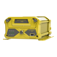
Bulkhead Mount.
Bulkhead Mount.Bulkhead Mount.
Bulkhead Mount.
Remove the two bracket mounting
screws.
Rotate camera mount 180° (upside
down) and reattach to base plate.
Microphone should be situated facing
floor.
Adjusti
AdjustiAdjusti
Adjusting the Field of View.
ng the Field of View.ng the Field of View.
ng the Field of View.
Adjust field of view by loosening the bracket mounting screws and rotating the camera mount
bracket. Ensure limited ceiling is seen in camera image. It is best to attach a TV monitor to
the NiTRO series or NiTRO-X series to capture the desired field of view of the camera, at
the same time the lens focus can be checked.
Focusing Camera Lens
Focusing Camera LensFocusing Camera Lens
Focusing Camera Lens.
..
.
Connect camera harness input to the back of the NiTRO series or NiTRO-X series and
power up the system.
Remove the Polycarbonate Dome cover and outer dome.
Connect the’ second video cable’ (available as part of
the Intermediate Kit: GSX
GSXGSX
GSX-
--
-NTR40X
NTR40XNTR40X
NTR40X-
--
-DPBK
DPBKDPBK
DPBK-
--
-Intermed Kit
Intermed KitIntermed Kit
Intermed Kit)
to the pin connector on the camera board and then to
the video input on a monitor a live video image will
display on screen to allow for easy lens adjustment.