- 54 -
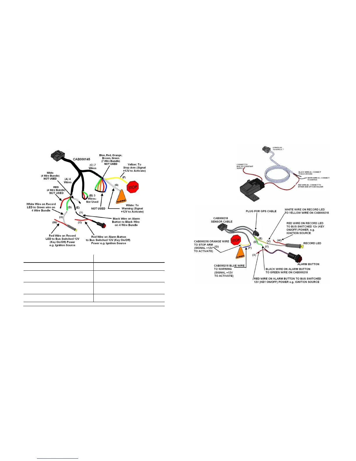
CAB000145: 7 Wire; 4 Wire and 3 Wire Terminations.
CAB000145: 7 Wire; 4 Wire and 3 Wire Terminations.CAB000145: 7 Wire; 4 Wire and 3 Wire Terminations.
CAB000145: 7 Wire; 4 Wire and 3 Wire Terminations.
Figure 41: CAB000145 Terminations.
A
AA
A
Alarm & LED Bundle (4 Wires; White &
Red. Not Used)
G
GG
G
White (7 Wire Bundle) to Warning
(Signal +12V to Activate).
B
BB
B
Speed Bundle (NOT USED) (3 Wires) V
VV
V
White Wire on Record LED Connect to
Green Wire (D) on 4 Wire Bundle.
C
CC
C
Trigger Bundle (7 Wires; Blue, Red,
Orange, Brown, Green. Not Used)
W
WW
W
Red Wire on Record LED to Bus
Switched 12V (Key On/Off) Power, e.g.
Ignition Source.
D
DD
D
Green (4 Wire Bundle) connect to White
(V) on Record LED.
X
XX
X
Red Wire on Alarm Button to Bus
Switched 12V (Key On/Off) Power, e.g.
Ignition Source.
E
EE
E
Black (4 Wire Bundle) connect to Black
(Y) Alarm Button.
Y
YY
Y
Black Wire on Alarm Button to Black
Wire (E) on 4 wire bundle.
F
FF
F
Yellow (7 Wire Bundle) to Stop Arm (Signal +12V to activate).
Table 10: CAB000145 Termination Definitions.
- 15 -
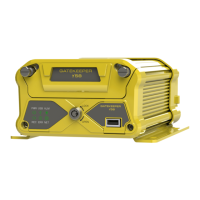
CAB00262 (6 PIN)
NiTRO-X DVR Power
Cable (30 feet long). See
Table 2 for Definitions and
Figure 2 for Connections.
Figure 2: CAB000218 Connections.
Recommended Location for Alarm Button
Recommended Location for Alarm ButtonRecommended Location for Alarm Button
Recommended Location for Alarm Button
The Alarm Button is generally mounted in a location that is within reach of the driver where
the drivers hand will naturally fall into place and its recommended location is towards the
front of the left switch panel.