DESCRIPTION
DESCRIPTIONDESCRIPTION
DESCRIPTION
PART NUMBER
PART NUMBERPART NUMBER
PART NUMBER
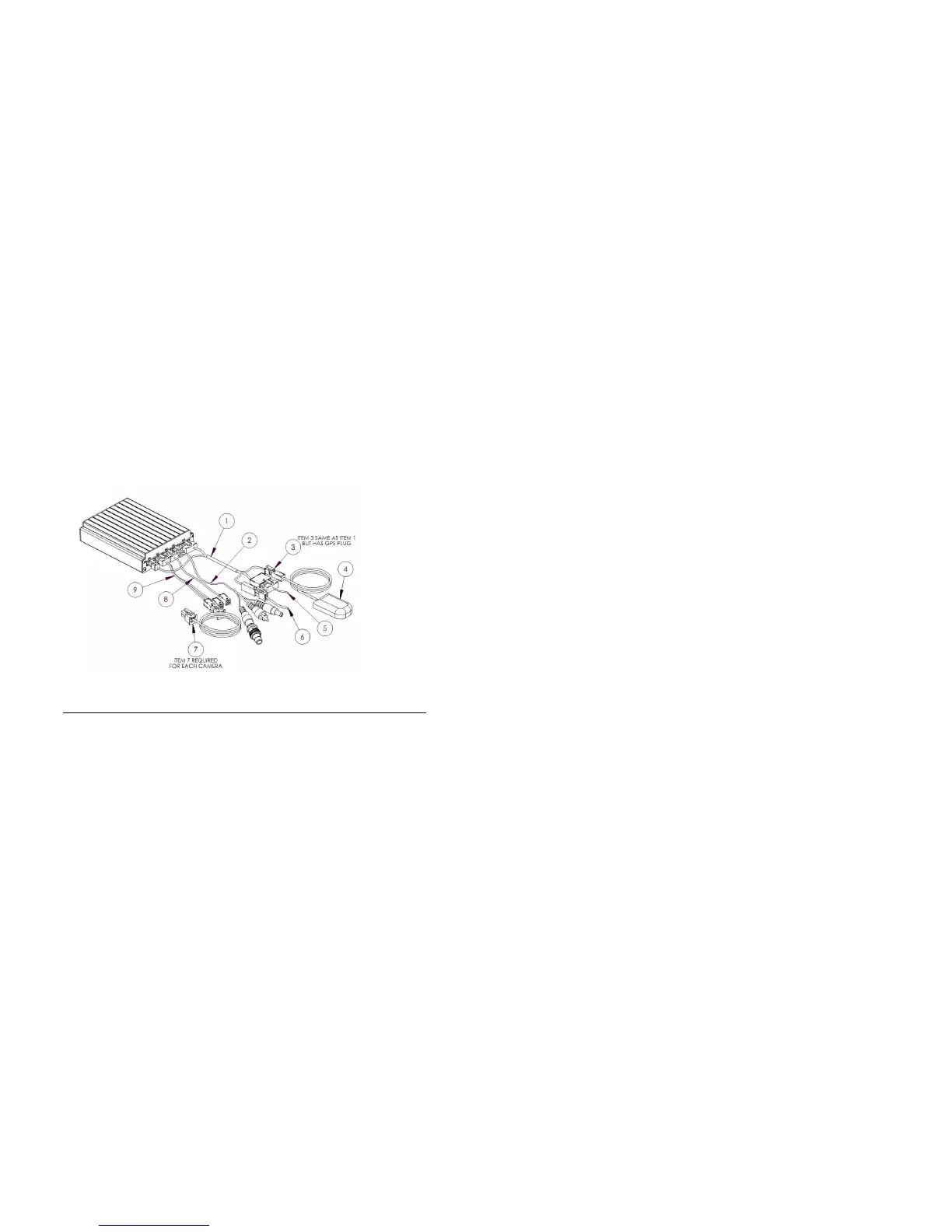
1 POWER SENSOR ADAPTER CABLE CAB000205
2 VIDEO OUT CABLE GSX-N40X/VIDEO/AUDIO OUT
ASSY
3 POWER SENSOR ADAPTER CABLE W/GPS CAB000206
4 GPS MODULE W/15’ CABLE DVRGPSN40X_ASSY
5 EXTERNAL TRIGGER CABLE CAB000145
6 POWER CABLE AND FUSE CAB000211
7 CAMERA CABLE 15’, 30’ OR 60’ CAB000142 or
GSWHC2N-XX
8 VIDEO ADAPTER CABLE 1 CHANNEL CAB000209
9 VIDEO ADAPTER CABLE 2 CHANNEL CAB000202
- 17 -
Leave enough cable slack at the Rear of the mounting bracket,12 inches.
Check For
Safety
Not blocking passenger or driver access.
Not obstructing driver’s view.
Will not snag loose clothing or carry-on items.
Accessibility.
To the DVR front panel for configuring.
For easy SD card removal and insertion.
For easy harness routing and connecting.
Routing the Power Harness.
Routing the Power Harness.Routing the Power Harness.
Routing the Power Harness.
CAB000
CAB000CAB000
CAB000219 (4pin NiTRO
219 (4pin NiTRO219 (4pin NiTRO
219 (4pin NiTRO
))
)) ))
)) or
oror
or
(
((
(CAB000
CAB000CAB000
CAB000262
262 262
262
(6pin NiTRO
(6pin NiTRO(6pin NiTRO
(6pin NiTRO-
--
-X
XX
X
)
))
)
Always use grommets when running the harness through sheet metal holes.
Avoid excessively tight bends especially around metal surfaces.
Use fuse holder and fuse provided on the 12V+ connection.
Connect fuse as close to power source as possible.
Use cable ties to secure harness and fuse holder.
Cut power harness to length, removing excess cable.
Use correct terminal size for wire gauge. Always use Butt or Ring Terminal
connectors.
10-12 AWG = Yellow
14-16 AWG = Blue
18-22 AWG = Red
Use ratcheting crimpers for terminal installation.
If grounding to a painted surface, scrape off paint and use ‘star’ washer between terminal
and metal surface.
DO NOT use painted or anodized fasteners.
Before connecting constant power, cut off excess slack.
Before connecting power directly at battery, verify that the system maintains a minimum of
8Volts during engine cranking. Testing requires starting the bus, with a multi-meter
connected to battery. Confirm voltage does not drop below 8V during cranking. If voltage
drops, advise mechanic at bus garage that the batteries may need to be replaced or a
Gatekeeper Systems PowerVault B maybe needed.
Routing the Sensor Harness
Routing the Sensor HarnessRouting the Sensor Harness
Routing the Sensor Harness
CAB000218
CAB000218CAB000218
CAB000218.
..
.
Route the TRIGGERS harness to the electrical panel.
Connect Orange lead to stop arm circuit
Connect Blue lead to warning lights circuit
Always use grommets when running the harness through sheet metal holes.
Avoid excessively tight bends especially around metal surfaces.