- 24 -
A:
A:A:
A: Portable LCD or DVD
B:
B:B:
B: NiTRO or NiTRO-X
C:
C:C:
C: Camera
D:
D:D:
D: GSWHC2N-XX Camera Harness, 15’; 30’ or 60’ lengths.
E:
E:E:
E: Yellow RCA Video Output to Video Input on Portable LCD or DVD Player.
F:
F:F:
F: Red RCA Audio Output to Audio Input on Portable LCD or DVD Player.
G0:
G0:G0:
G0: 4 Pin Female connector on CAB000157 connects to G1
G1G1
G1 4 Pin Male connector on
Camera Harness (D
DD
D).
H0
H0H0
H0 4 Pin Male Connector connects to H1
H1H1
H1 4 Pin Female Connector on Camera Harness (D)
K0
K0K0
K0 4 Pin Male Connector on CAB000157 Connects to K1
K1K1
K1 CAB000202 (Dual Channel) or
CAB000209 (Single Channel) Camera Adapter Harness.
Please Note:
Please Note:Please Note:
Please Note: On a multi-camera system using CAB000202 K0
K0K0
K0 should be connected to each
additional K1
K1K1
K1 Camera Adapter Harness, e.g. CH02; CH03 and/or CH04 to ensure complete
alignment of all connected cameras.
M:
M: M:
M: Camera Adapter Harness (CAB000202) systems only Connect K0
K0K0
K0 to align and adjust
additional cameras.
Table 4: Video Alignment Cable Connection Descriptions.
An installed, fully functional, powered up NiTRO or NiTRO-X is required when using
CAB000157, Video Alignment Cable. When using the Video Alignment Cable CAB000157
there are only four connections to make, one of which, the Audio connection, is optional.
If you look at the Video Alignment Cable you will see that there are three cables coming from
one end of the Video Alignment Cable and a single cable coming from the other end.
3 Cables.
3 Cables.3 Cables.
3 Cables.
Yellow Video RCA for connection to the LCD or DVD players Video Input connection. This is the
connection which will display the image being captured by the camera which is currently being
aligned.
Red Audio RCA for connection to the LCD or DVD players audio input. This connection is
optional, though if you wish to record audio from the channel it is advised that this be
connected.
A four pin male connector which connects to CAB000202 or CAB000209 Camera Adapter
harness connected to the rear of the NiTRO or NiTRO-X
Single Cable.
Single Cable.Single Cable.
Single Cable.
The single cable coming from the other end of the Video Alignment Cable is a 4 pin female
connector which connects to the harness of an installed camera.
Once these connections are made, alignment of the camera can be completed.
- 45 -
GPS.
GPS.GPS.
GPS.
Please note:
Please note:Please note:
Please note: Only NiTRO 400 or NiTRO-X 400 series systems which have a GPS module
attached can access GPS information.
To fully utilize the GPS feature within MaxVIEW
an active internet connection is required. From
the main window of MaxVIEW click on View and
then select GPS Mapping and then choose Show
Map. There will be a slight time delay as
MaxVIEW synchronizes the GPS data.
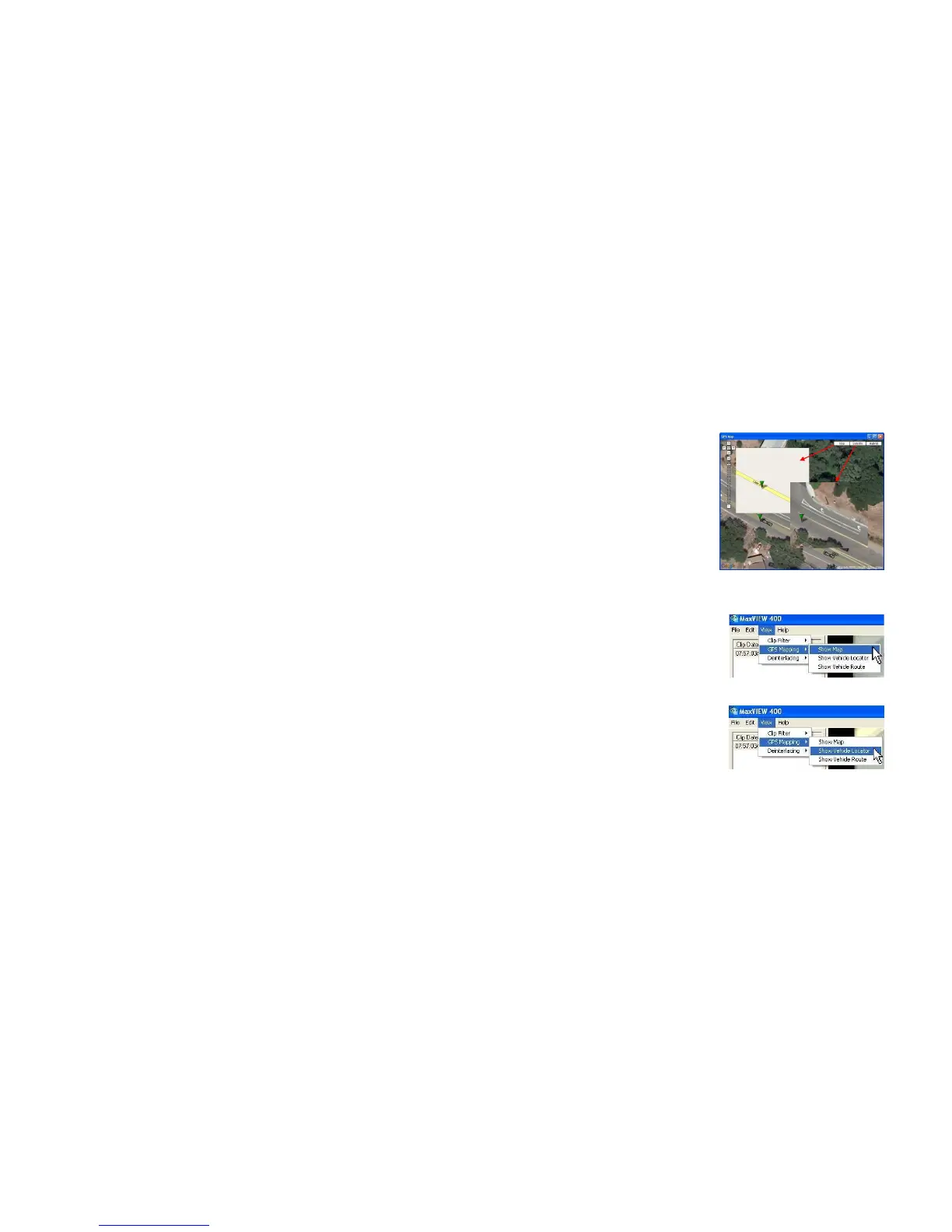
Once synchronization has completed MAP view
will initially be displayed and this can be changed
by selecting one of the other two options at the
top right of the screen; Satellite or Hybrid, Figure
27.
Figure 27: GPS Map; Satellite; Hybrid Features.
GPS Mapping Options.
GPS Mapping Options.GPS Mapping Options.
GPS Mapping Options.
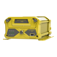
With a new install of MaxVIEW™ the default is not
to display the GPS Mapping Options, these have to
be set. In MaxVIEW™. Select the View menu, next
choose GPS Mapping and then select Show Map
(Figure 28). This will bring up the window to the
right of the main MaxVIEW™ window. This GPS
data mapping window, (Figure 27) is moveable and
resizable.