GASMAX/TX Operation & Maintenance Manual, Revision 1.0
Page 22
POWER AND SIGNAL WIRING
The GASMAX/TX is completely self-contained. Power is provided by the internal 3.6V battery, and output
data is sent entirely via wireless transmission from the local or remote antenna.
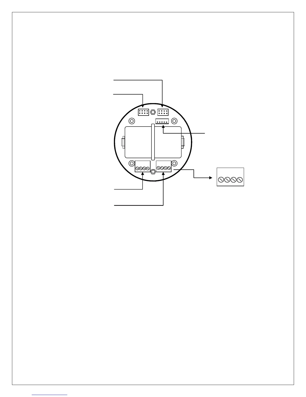
Figure 7-1: GASMAX/TX I/O Battery Board
The multi-pin interface cable from local senor heads connects to “S1” for channel 1 and to “S2” for
channel 2. Four-wire sensor extension cables for remote sensors connect to “TB-1” for channel 1 and to
“TB-2” for channel 2. When replacing the battery be careful to double-check the polarity before installing.
Reversing the polarity will damage the internal electronics.
CONNECTING A REMOTE ANTENNA
Additional information on remote antennas will be available in a future version of the GASMAX/TX
manual.
1000-2721 LITHIUM BATTERY
OBSERVE POLARITY
WHEN REPLACING
Board to Display Module
SCL
SDA
COM