GASMAX/TX Operation & Maintenance Manual, Revision 1.0
Page 23
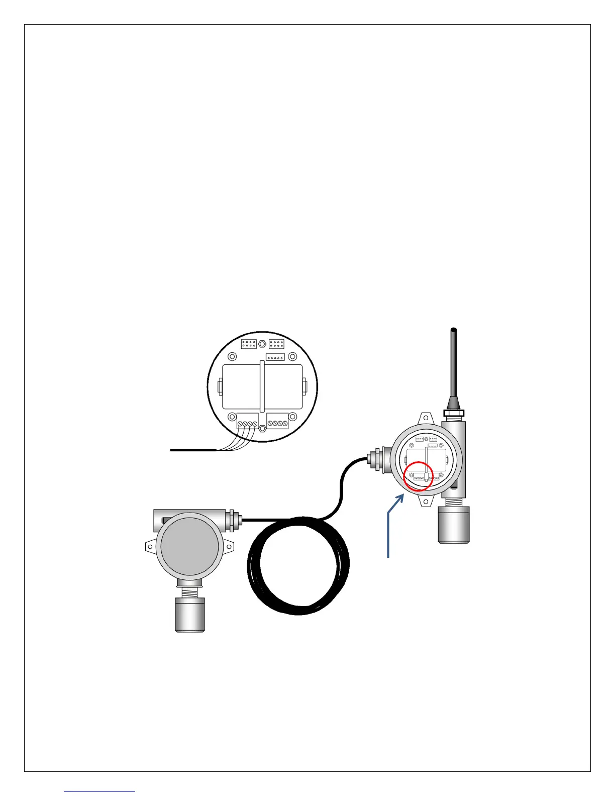
CONNECTING A GASMAX/TX REMOTE SENSOR
The GASMAX/TX remote sensor consists of a cast aluminum explosion-proof junction box, stainless steel
sensor head and 15’ / 3m length data cable. The junction box contains a PCB with connection point for the
sensor head cable and wiring terminals for the four-wire digital data cable connection to the GASMAX/TX
display enclosure. Fittings are ¾” NPT. The sensor head should ALWAYS be mounted vertically as shown,
and GDS Corp recommends side entry for all conduit runs.
NOTE: THE SENSOR SEPARATION KIT DATA CABLE CAN BE CUT TO ANY LENGTH FROM THE 15 FT / 3M
CABLE PROVIDED. THE DATA CABLE SHOULD NOT BE LENGTHENED.
GASMAX/TX monitors with remote-mount sensors are shipped as separate pieces and must be assembled
by the customer. The data cable connects to the I/O battery board in the GASMAX/TX, using “TB1” for
channel 1 and “TB2” for channel 2. Connect the VCC, SCL (serial clock), SDA (serial data) and Common as
shown.
Figure 7-2: Connecting a GASMAX/TX Remote Sensor
Connect to TB1 for remote
sensor on channel 1, TB2 for
remote sensor on channel 2