GASMAX/TX Operation & Maintenance Manual, Revision 1.0
Page 25
8 INITIAL SETUP
POWER-ON AND USER INTERFACE
To turn on the GASMAX/TX hold the magnetic wand over the UP/ON key
for several seconds. The welcome screen will appear, followed by the
sensor information screen. The GASMAX/TX will then enter a predefined
warm-up delay period to allow the sensor to stabilize. If the unit does not
power up properly, check for a loose battery connection or dead battery.
NOTE: GDS CORP RECOMMENDS APPLYING POWER TO THE GASMAX/TX
AFTER THE SITE MANAGER SYNCHRONIZING BEACON SIGNAL IS ACTIVE.
BATTERY LIFE IS REDUCED IF THE GASMAX/TX IS ON FOR LONG PERIODS
WHILE UNABLE TO COMMUNICATE TO THE MASTER DEVICE.
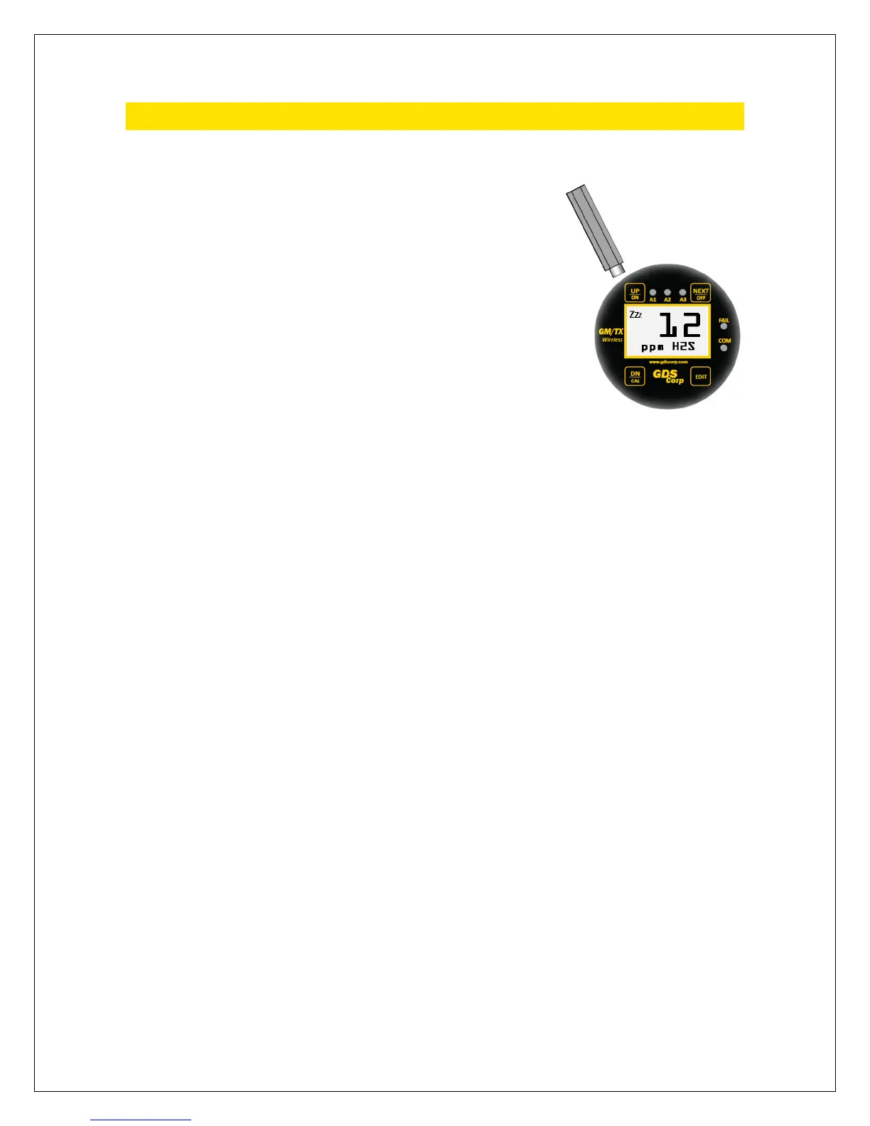
The GASMAX/TX display is shown in Figure 8-1. There are four magnetic
switches on the face of the GASMAX/TX, arranged in a quadrant around the LCD display labeled “NEXT”,
“EDIT”, “DOWN/CAL” and “UP/ON”. To activate, or “press” a magnetic switch, swipe the magnet near the
switch. To access the Main Menu, press the “EDIT” key while in display mode. Pressing the NEXT key
causes the GASMAX/TX display to switch display screens between DATA and TREND displays. Activating
DOWN/CAL, followed by EDIT, while in display mode initiates Calibration Mode.
The EDIT key activates the USER MENU display mode. When in user menu display mode, use UP and
DOWN to select an item, EDIT to change an item, and NEXT to exit the menu or function and return the
GASMAX/TX to display mode. For the balance of this manual, the term “press” will be used to describe
activation of any key via the magnetic wand. See Chapter 11 for a detailed description of the User Menu.
All that is necessary to integrate a GASMAX/TX into a GDS Corp wireless network is to select the Network
Identifier and Device ID. Each device in any given GDS Corp wireless network should have the same
Network Identifier, and each GASMAX/TX should have a different Device ID.
To access the necessary menu, press EDIT and select the Device Setup – RF Link Setup Menu. See Figure 8-
2 for a step-by-step procedure to integrate multiple GASMAX/TX devices with a C2/TX Wireless Site
Manager.
To turn the GASMAX/TX OFF, access the Device Setup – Turn Power Off menu, or hold the magnet over
the NEXT key until the display shows “EDIT to Accept, and then press the EDIT key.
MAGNET OVER UP/ON KEY
FOR SEVERAL SECONDS