GASMAX/TX Operation & Maintenance Manual, Revision 1.0
Page 31
10 OPERATION AND MAINTENANCE
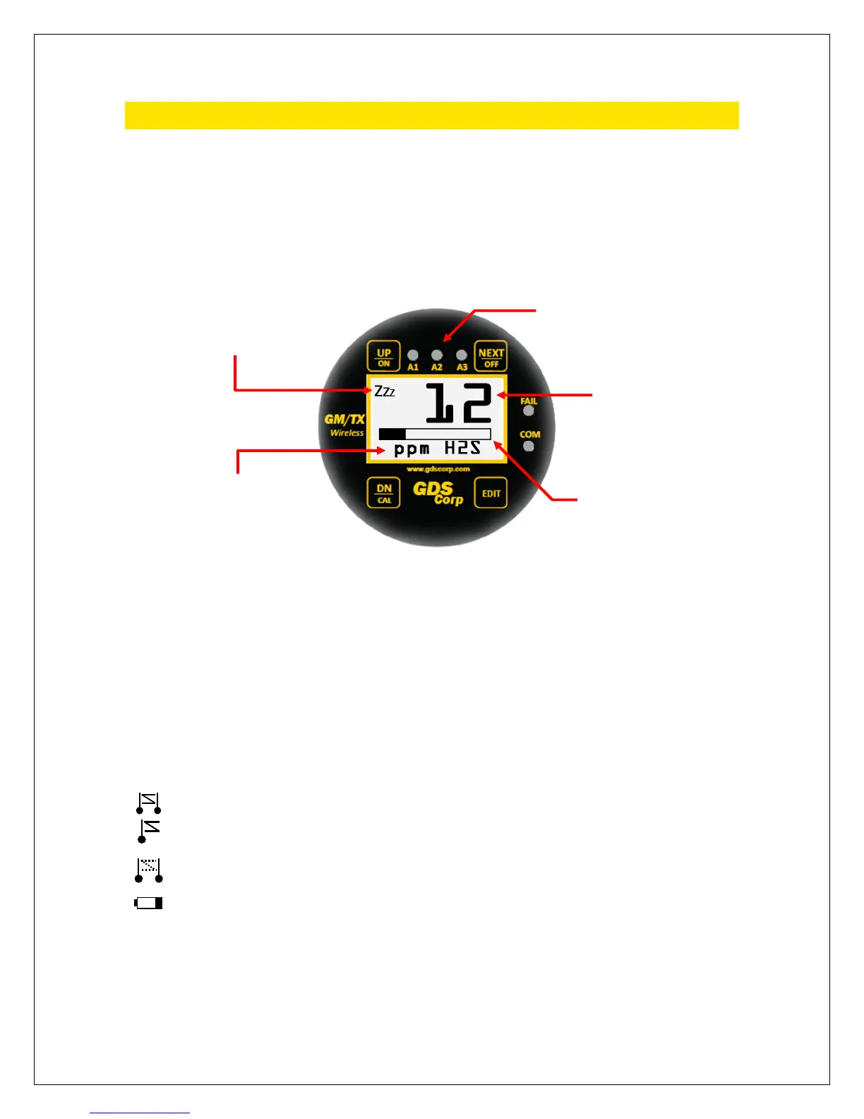
DATA DISPLAY SCREEN
The DATA display screen shows real-time channel value information in calibrated engineering units. A
horizontal bar graph tracks the current value and shows the Alarm 1 and Alarm 2 values in graphical form.
In single-channel display mode, user-programmable Engineering Units (“Eunits”) and Measurement Name
text strings are shown below the real-time reading.
Figure 10-1: GASMAX/TX Data Display Screen
A “Wireless Status Icon” appears in the upper left corner of the data display screen to indicate the status
of the wireless interface. The information shown includes:
Indicates that the GASMAX/TX microprocessor is in low-power sleep mode.
Indicates that the GASMAX/TX microprocessor is awake and reading the sensor data.
synchronize with the beacon.
Indicates that the beacon was successfully detected and that a data transmission is in progress.
that the beacon signal was not received during the most recent attempt to transmit
data. The GASMAX/TX will not attempt to transmit until a beacon signal is present.
Indicates a “Range Warning”. This icon is presented if the server was previously out o
any reason and can be reset using the Device Setup – Reset Range Icon menu.
Low battery indication. Displayed during each “sniff cycle’ if the battery is near the end of its
useful life.
S
NIFF
RNG
LoBat
Wireless Status Icon
Alarm LEDs (Flash when active)
Bargraph
Engineering Units
Calibrated Gas Value