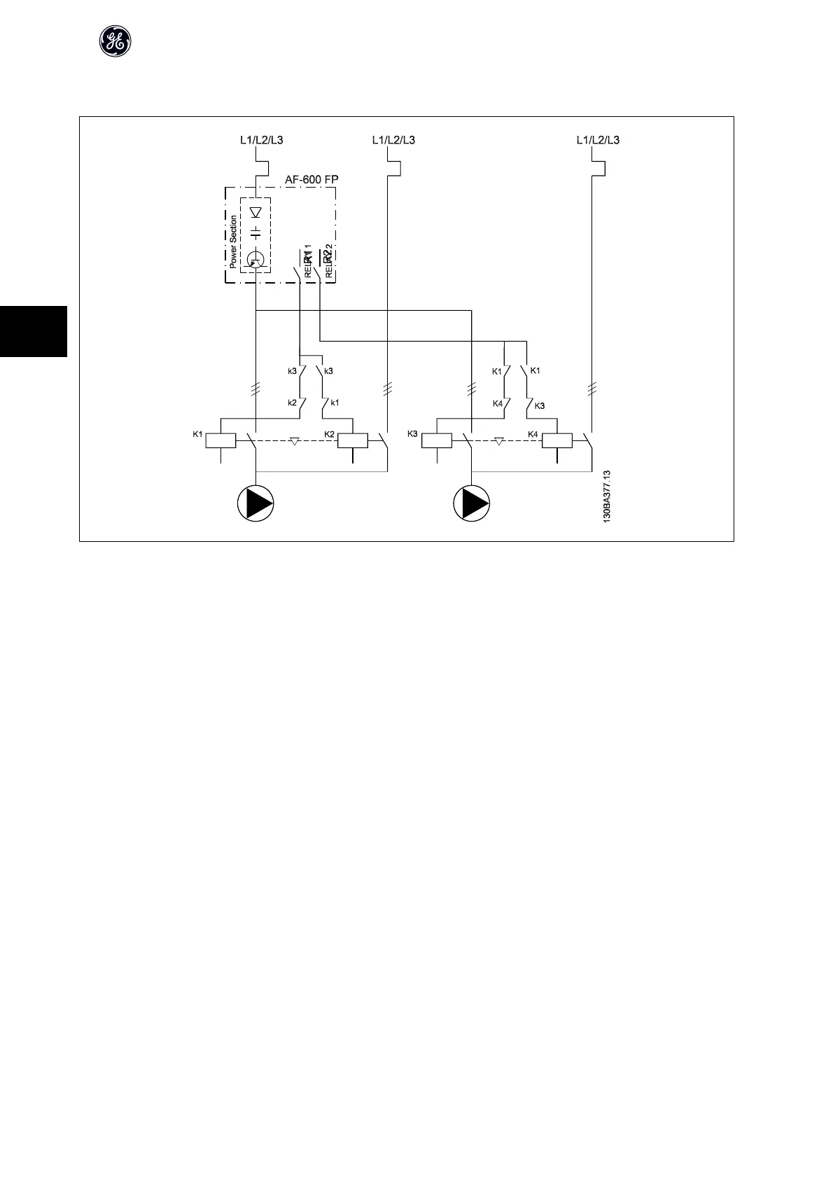
5.1.12 Lead Pump Alternation Wiring Diagram
Every pump must be connected to two contactors (K1/K2 and K3/K4) with a mechanical interlock. Thermal relays or other motor protection devices must be
applied according to local regulation and/or individual demands.
• RELAY 1 (R1) and RELAY 2 (R2) are the built-in relays in the frequency converter.
• When all relays are de-energized, the first built in relay to be energized will cut in the contactor corresponding to the pump controlled by the relay. E.g.
RELAY 1 cuts in contactor K1, which becomes the lead pump.
• K1 blocks for K2 via the mechanical interlock preventing mains to be connected to the output of the frequency converter (via K1).
• Auxiliary break contact on K1 prevents K3 to cut in.
• RELAY 2 controls contactor K4 for on/off control of the fixed speed pump.
• At alternation both relays de-energizes and now RELAY 2 will be energized as the first relay.
AF-600 FP Design Guide
102
5

 Loading...


