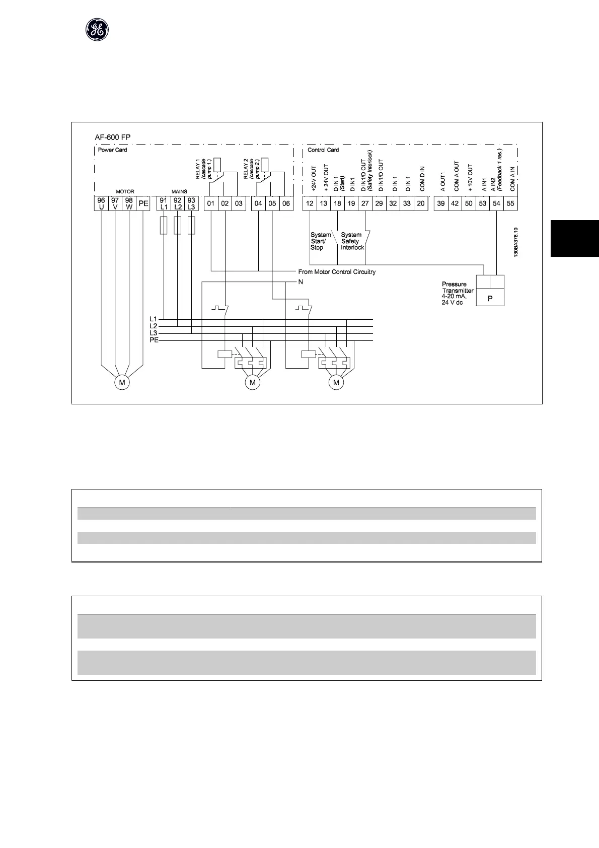
5.1.13 Cascade Controller Wiring Diagram
The wiring diagram shows an example with the built in BASIC Cascade Controller with one variable speed pump (lead) and two fixed speed pumps, a 4-20 mA
transmitter and System Safety Interlock.
5.1.14 Start/Stop Conditions
Commands assigned to digital inputs. See Digital Inputs, parameter group ID-40.
Variable speed pump (lead) Fixed speed pumps
Start (SYSTEM START /STOP) Accels (if stopped and there is a demand) Staging (if stopped and there is a demand)
Lead Pump Start Accels if SYSTEM START is active Not affected
Coast (EMERGENCY STOP) Coast to stop Cut out (built in relays are de-energized)
Safety Interlock Coast to stop Cut out (built in relays are de-energized)
Function of buttons on keypad:
Variable speed pump (lead) Fixed speed pumps
Hand Accels (if stopped by a normal stop command) or
stays in operation if already running
Destaging (if running)
Off Decels Decels
Auto Starts and stops according to commands via ter-
minals or serial bus
Staging/Destaging
AF-600 FP Design Guide
103
5

 Loading...


