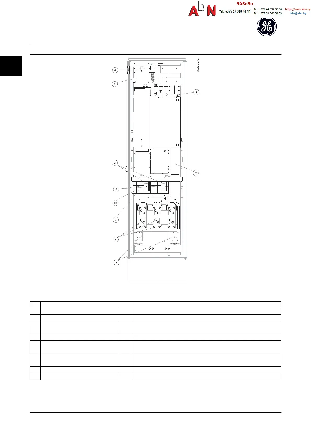
Figure 1.6 Rectifier Cabinet, unit sizes 61, 62, 63 and 64
1) 24 V DC, 5 A 5) Load sharing
T1 Output Taps -DC +DC
Temp Switch 88 89
106 104 105 6) Control Transformer Fuses (2 or 4 pieces). See 13.3 Fuse Specifications for part
numbers
2) Manual Motor Starters 7) SMPS Fuse. See 13.3 Fuse Specifications for part numbers
3) 30 A Fuse Protected Power Terminals 8) Manual Motor Controller fuses (3 or 6 pieces). See 13.3 Fuse Specifications for part
numbers
4) Line 9) Line Fuses, unit sizes 61 and 62 (3 pieces). See 13.3 Fuse Specifications for part
numbers
R S T 10) 30 Amp Fuse Protected Power fuses
L1 L2 L3
Table 1.5
Introduction
AF-650 GP
TM
Design and Installation Guide
1-6 DET-767A
1

 Loading...


