CAUTION
Thermistors must use reinforced or double insulation to
meet PELV insulation requirements.
Parameters
Function Setting
F-10 Electronic
Overload
[2]
Thermistor
trip
F-12 Motor
Thermistor Input
[1] Analog
input 53
* = Default Value
Notes/comments:
If only a warning is desired,
F-10 Electronic Overload should
be set to [1] Thermistor warning.
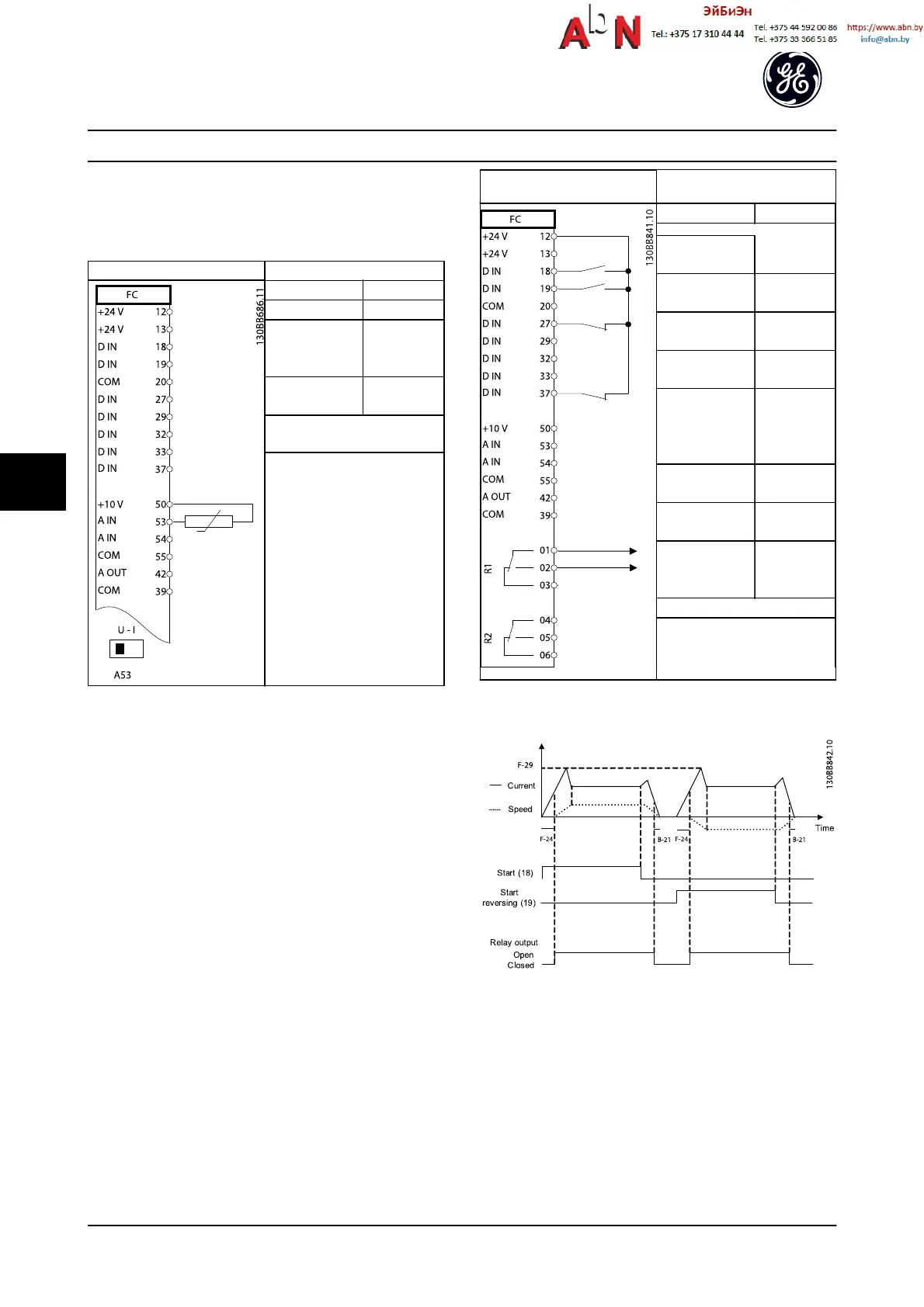
Table 6.10 Motor Thermistor
Parameters
Function Setting
E-24 Function
Relay
[32] Mech.
brake ctrl.
E-01 Terminal 18
Digital Input
[8] Start*
E-02 Terminal 19
Digital Input
[11] Start
reversing
F-24 Holding
Time
0.2
F-25 Start
Function
[5] Advanced
Vector
Control/FLUX
Clockwise
F-29 Start
Current
Im,n
B-20 Release
Brake Current
Application
dependent
B-21 Activate
Brake Speed
[RPM]
Half of
nominal slip
of the motor
* = Default Value
Notes/comments:
Table 6.11 Mechanical Brake Control
Figure 6.4
In the upper right corner of the keypad, two numbers are
shown, e.g. 1(1). The number outside the parenthesis is the
active setup and the number inside the parenthesis is the
setup which will be edited. Default will always be 1(1).
Make sure you edit setup 1.
Application Setup Examples
AF-650 GP
TM
Design and Installation Guide
6-4 DET-767A
6

 Loading...


