Installation Instructions
DIMENSIONS AND CLEARANCE
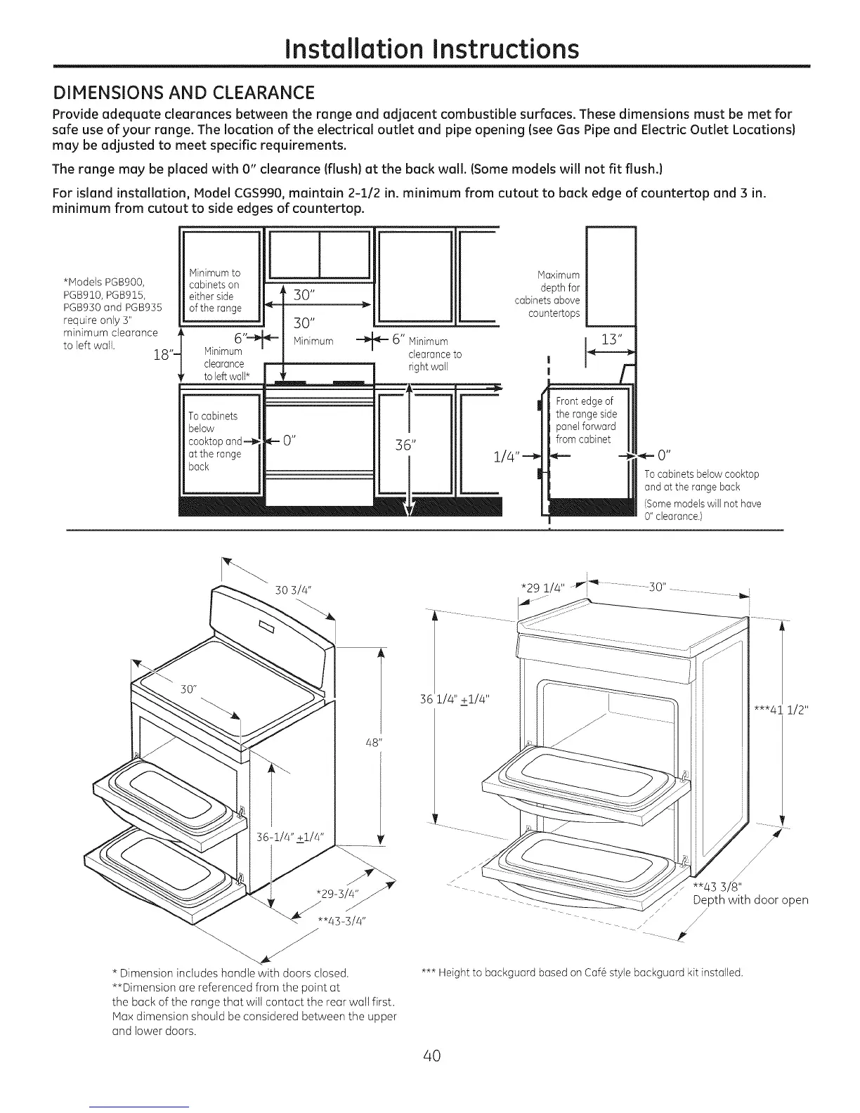
Provide adequate clearances between the range and adjacent combustible surfaces. These dimensions must be met for
safe use of your range. The location of the electrical outlet and pipe opening (see Gas Pipe and Electric Outlet Locations)
may be adjusted to meet specific requirements.
The range may be placed with 0" clearance (flush) at the back wall. (Some models will not fit flush.)
For island installation, Model CGS990, maintain 2-1/2 in. minimum from cutout to back edge of countertop and 3 in.
minimum from cutout to side edges of countertop.
*Models PGB900,
PGB910, PGB915,
PGB950 and PGB955
require only 5"
minimum clearance ,
to left wall. 28"-
Minimumto
cabinets on
either side
of the range _--
6"-_
Minimum
clearance m
toleft waN*
To cabinets
below
eooktop and --ID
at the range
back
30"
30"
Minimum "-_
m m
IM-O"
6" Minimum
clearance to
right wall
Maximum
depth for
cabinetsabove
countertops
' r
Front edge of
the rangeside
panel forward
from cabinet
0"
Tocabinets below cooktop
and at the rangeback
(Somemodels will not have
0" clearance.)
48"
"29-3/Q" _
*'43-3/4"
* Dimension includes handle with doors closed.
**Dimension are referenced from the point at
the back of the range that will contact the rear watt first.
Max dimension should be considered between the upper
and lower doors.
i
*29 !/4" P'_I"q_.............. 30"
112"
"_ Depth with door open
*** Height to backguard based on Caf6 style backguard kit installed.
40