3. Technical specifications
3-2. I/O terminal board specifications
Power I/O terminals
Terminal Function Description
1L1, 3L2, 5L3 Mains Input 3ph input voltage according ASTAT Plus type.
2T1, 4T2, 6T3 Motor output Output terminals to 3ph AC motor
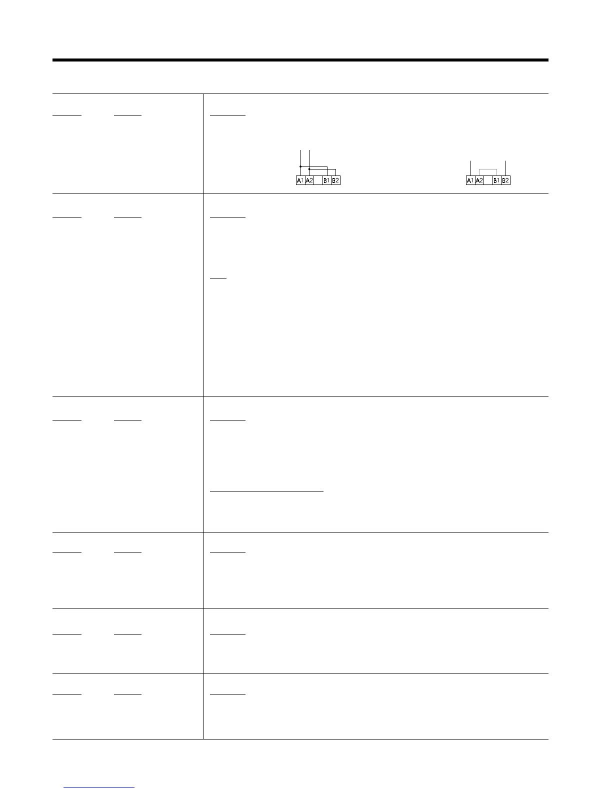
A1, A2, B1, B2 Input Control Voltage 110/120V AC, +10%, -15%: ; 220/240V AC, +10%, -15%:
Digital Inputs
Terminal Function Description
57 Common for digital inputs This is a common terminal for the digital input terminals specified below.
1 Run Run order. Command signal may be provided by one NO dry momentary contact to terminals 1 and 57.
2 Stop Stop order. Command signal may be provided by one NC dry momentary contact to terminals 2 and 57.
Note: Run/Stop permanent command is allowed linking 1-57 and using one dry NO contact to 2-57
terminals.
3 Programmable input I3 These two inputs are programmable. Can be assigned to the following internal functions
4 Programmable input I4
-soft stop -DC brake -Linear Ramp
-pump control -slow speed control -dual ramp selection
-kick start -reverse slow speed -bypass function
-override -local / remote control
Command signal should be provided by one NC dry contact to terminals 57-3 or terminals 57-4. By switching
this contact ON / OFF it is possible to enable or disable the assigned function.
Digital Outputs
Terminal Function Description
11, 12, 14 Programmable relay1r 11-12 = NC, 11-14 = N.O. dry contacts. This relay can be assigned to several internal output functions. (p. 3.6)
As default assigned to function RUN
23, 24 Programmable relay 2r 23-24 = N.O. dry contact. This relay can be assigned to several internal output functions. (page 3-6)
As default assigned to function EOR
33, 34 Programmable relay 3r 33-34 = N.O. dry contact. This relay can be assigned to several internal output functions. (page 3-6)
As default assigned to function DC BRAKE
Common for all relay output contacts Maximum usage voltage: 380VAC (B300-UL)
Thermal current: 8A.
AC-15 use: 220V / 3A, 380V / 1A
DC-15 use: 30V max/ 3.5A
Analog I/O
Terminal Function Description
8 Analog input common (-) This is a common terminal for the analog input terminal number 7, and analog output termnal number 9.
7 TG feedback input (+) 0-5V analog input for speed feedback. It should be provided by a DC tacho-generator coupled to the motor.
This speed feedback signal is required when the "linear ramp" function is used.
9 Current Output (+) 0-10V DC analog Output for current measurement purpose. Ir correspond to 2V DC
Load Impedance 10KΩ or higher
Motor thermistor terminals
Terminal Function Description
5 , 6 Motor thermistor input This input allows a motor thermistor with a response value from 2,8 to 3,2KΩ , and a reset value from 0,75 to
1KΩ to control motor temperature.
When the motor thermistor is not used, a link must be used in terminals 5-6.
Communications
Terminal Function Description
SG, TD, RD Gr, Tx, Rx data RS232C, 3 wires, half duplex. Maximum cable length 3mts (10 feet)
Asynchronous data transmission, 9600 Bauds, 1 bit start, 8 bits data, 2 bits stop. no parity
ASCII and ModBus RTU protocols selectable from keypad as standard. (Check appendix 6-2)
Profibus DP and DeviceNet by external optional accessory
3-2