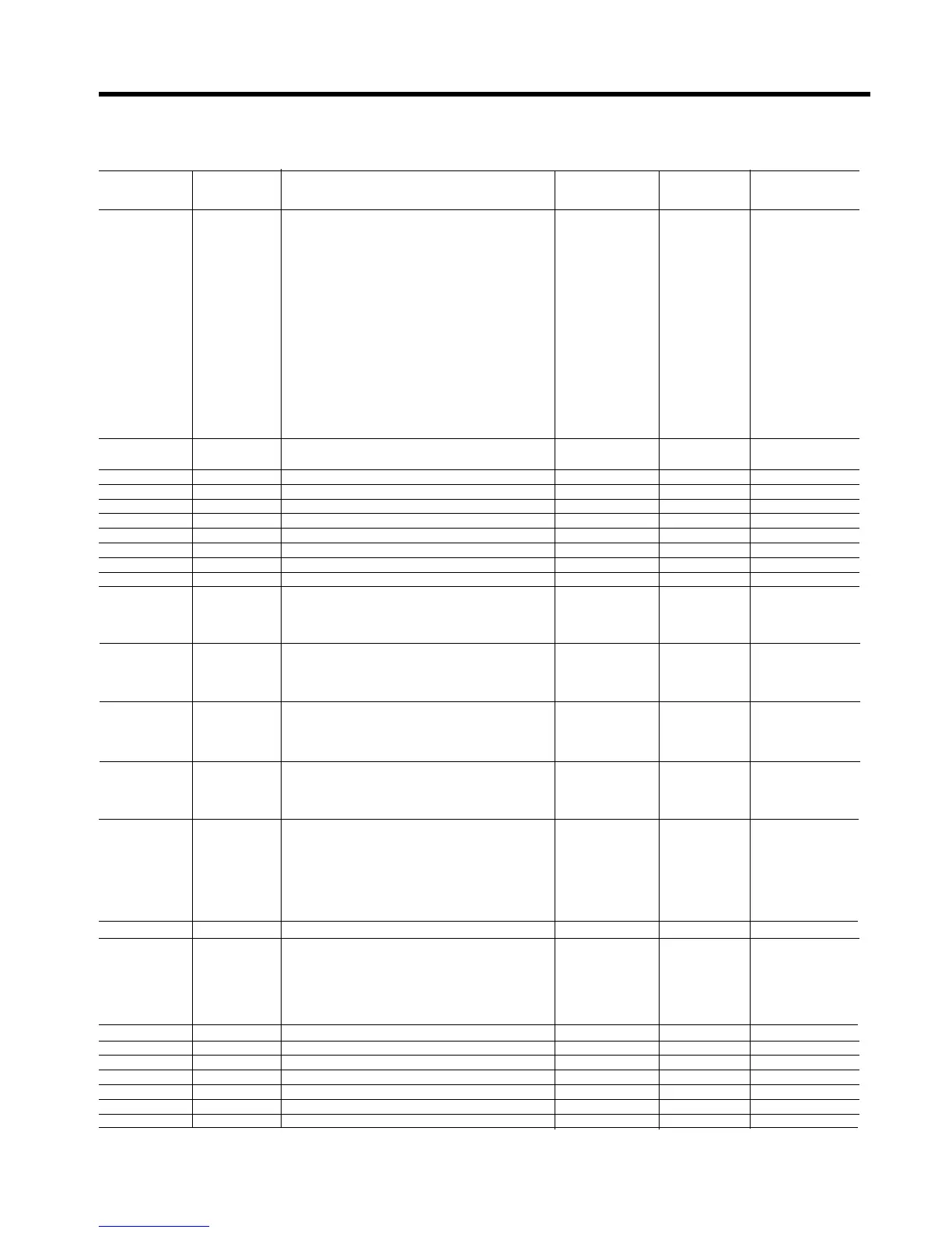
Parameter Parameter Function Read/Write Range Comments
number name (R/W)
0 Status Soft starter status R/- 0 - 14 0: ON
1: STOP
2: LOCK
3: Alarm (errors)
4: PULS
5: RAMP
6: FULL
7: SAVE
8: SOFT
9: DCBK
10: FULL (override)
11: Not used
12: INCH
13: TACH
14: PUMP
1 M Motor current R/-
(%N or Amps, depending on UF parameter)
2 N Nominal motor current (% Unit current) R/W 40-120
3 L Limit current (% In) R/W 100-700
4 T Starting torque (% DOL torque) R/W 10-90
5 a Acceleration ramp time (sec) R/W 1-99
6 d Deceleration ramp time (sec) R/W 1-120
7 p Kick start time (msec) R/W 0-999
8 b DC brake time (sec) R/W 0-99
9 I DC brake current (% In) R/W 50-250
10 S Soft stop control R/W 0-3 0: OFF
1: ON
2: I3
3: I4
11 C Pump control R/W 0-3 0: OFF
1: ON
2: I3
3: I4
12 P Kick start control R/W 0-3 0: OFF
1: ON
2: I3
3: I4
13 F Override R/W 0-3 0: OFF
1: ON
2: I3
3: I4
14 B DC brake control R/W 0-6 0: OFF
1: ON
2: I3
3: I4
4: PON
5: PI3
6:PI4
15 LK Lockout (min.) R/W 0-45
16 o Overload trip curve R/W 0-5 0: OFF
1: N1
2: N2
3: N3
4: C1
5: C2
17 internal use
18 W Write EEPROM -/W 1
19 R Read EEPROM -/W 1
20 - internal use
21 v Software version R/- xxx vxxx
22 - internal use
23 - internal use
6. Appendix
6-2-5. List of parameters that can be controlled by the serial interface
6-9