5-3. Start-up
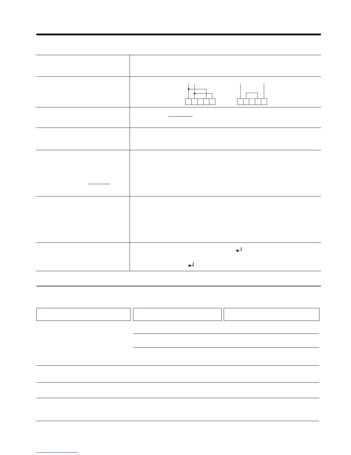
- Make sure equipment wiring corresponds to
one of the recommended routing diagrams or
equivalent
- If the motor has thermal protection sensor, remove the link between terminals
5 and 6 prior to wire the sensor
- Make sure the control wire harness corre-
sponds to the control voltage used.
- Adapt equipment rated current to motor, setting
the motor current In
Factory setting
N 1 0 0
N x x x ; x x x =
In (motor)
Ir (unit)
x 100
Factory setting
o C1
oxxx ; xx x OFF = disabled (extermal overload relay must be used
C1/C2 = IEC Class 10 or Class 20
N1/N2/N3= Nema 10, 20 or 30
Factory setting
Starting torque T _ x x T _ 20
Acceleration ramp time a x x x a _ 2 0
Kickstart P ON/OFF/I3/I4 P OFF
Kickstart time p x x x (if P enabled) P 1 0 0
Current limit L x x x L 3 0 0
L x x x =
Im (start)
In (motor)
x 100
Factory setting
Soft stop S ON/OFF/I3/I4 S OFF
Decceleration ramp time d x x x d _ 2 0
DC injection brake B ON/OFF/I3/I4 B OFF
DC braking time b _ x x (if B enabled) b _ _ 5
DC braking current I x x x (if B enabled) I 5 0
- Set braking parameters as needed :
- Set overload trip curve as needed
- Set starting parameters as needed :
- Set parameter K to ON (ON = 69 + )
- Set parameter W to ON
- Press (parameter W is set to OFF automatically)
If you change the default configuration and wish
to keep it, remember to rewrite the parameters
in E2PROM as follows :
- Send run command to equipment and make sure that operation is correct.
110/120V ac
220/240V ac
A1 A1A2 A2B1 B1B2 B2
5. Installation
Display OFF
Symptom or Error Possible Cause Measures to be taken
Check wire harness and control voltage
No control voltage
F1 fuse blown on power supply PCB
Check and change, page 6-8
Verify connectorsBad connection of flat wire joining power
supply PCB to control PCB
F2 fuse blown on power supply PCB
Check and change, page 6-8
Check 1L1 phase and/or mains frequence
No 1L1 phase or frequence is out of range
Excesive load or excesive current during starting
Verify overload conditions during starting time and steady
state.
Check settings in parameters "Nxxx", "Lxxx", and "oxxx"
Overload trip
Equipment does not respond to
STOP / START controls
Frequency error
(admits 45Hz
≤ ≤
≤ ≤
≤ f main
≤ ≤
≤ ≤
≤ 65Hz)
5-4. Troubleshooting
5-3