3-3. I/O Wiring
3. Technical specifications
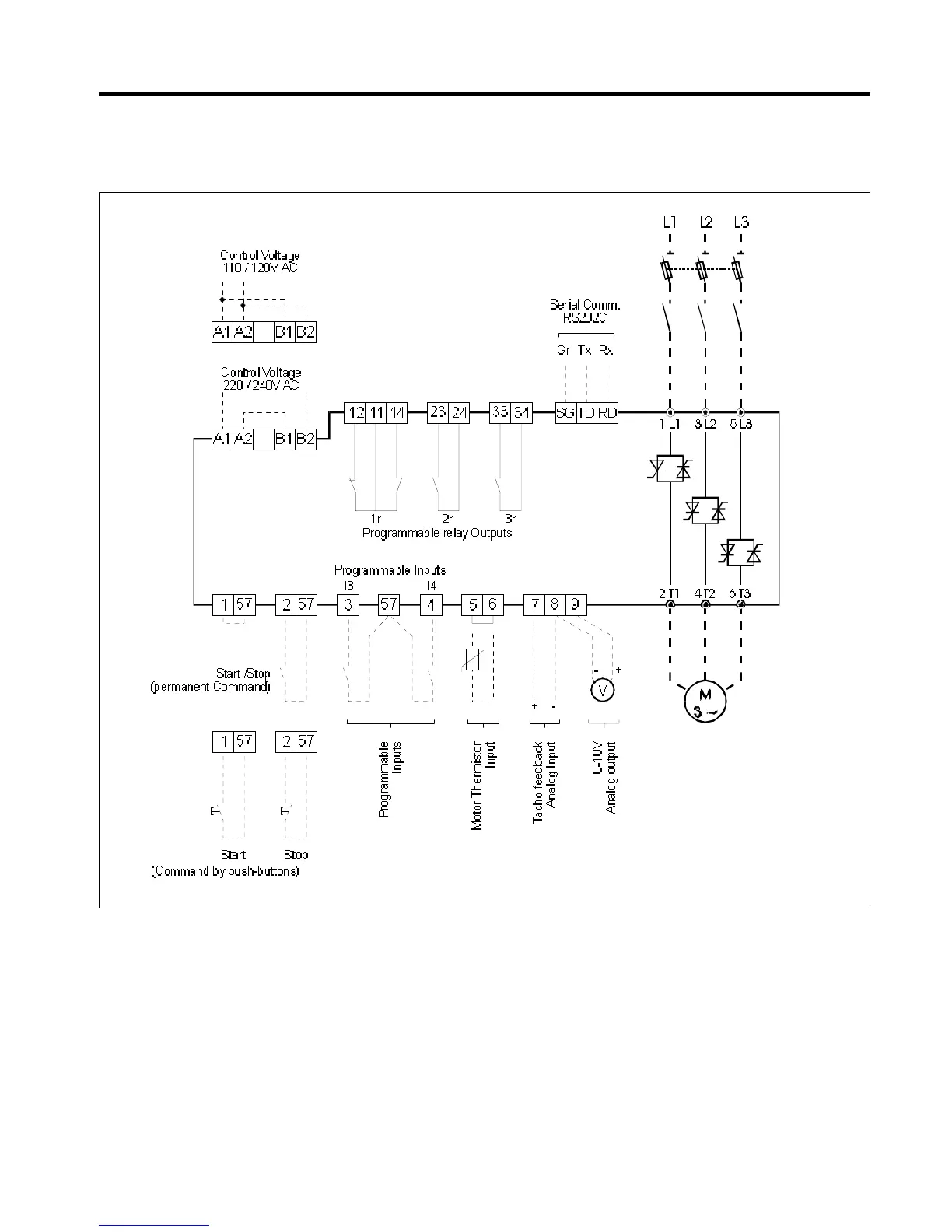
ASTAT Plus's terminal layout and wiring configuration is shown in the diagram of below
(1*)
(1*)
(3*)
(2*)
Notes: (1*) Control and Mains wiring recommendations are given in chapter 5.
(2*) The programmable inputs I3, I4 are not assigned to any function as default. Check pages 3-6 prior to using these inputs.
(3*) The programmable relay outputs are assigned to the following functions as default:
Relay (1r): RUN, (RUN status)
Relay (2r): EOR, (End of Ramp)
Relay (3r): DCBR, (DC Braking control)
(4*) Important: Use dry contacts only
3-3
(4*)
(4*)