47 • Installation
5. INSTALLATION
Do not interchange line and load connections
When mains voltage is connected to the ASTAT-XT, even if control voltage is
disconnected, full voltage may appear on the ASTAT-XT’s load terminals.
Therefore if isolation is required you must connect an isolation device between the
mains and the ASTAT-XT.
WARNINGS
Power factor correction capacitors must not be installed on the load side of the
ASTAT-XT. When required, install capacitors on the line side of the ASTAT-XT.
5.1 Prior to Installation
Check
that the Full Load Ampere (Im) of the motor is lower than or equal to the Current Rating in the expected load
duty (LD or HD) indicated on the side and/or front name plate of the ASTAT-XT.
Note that Current Rating indicated as LD corresponds to load duty NEMA Class 10; Current Rating indicated as HD
corresponds to load duty IEC Class 20 or NEMA Class 30.
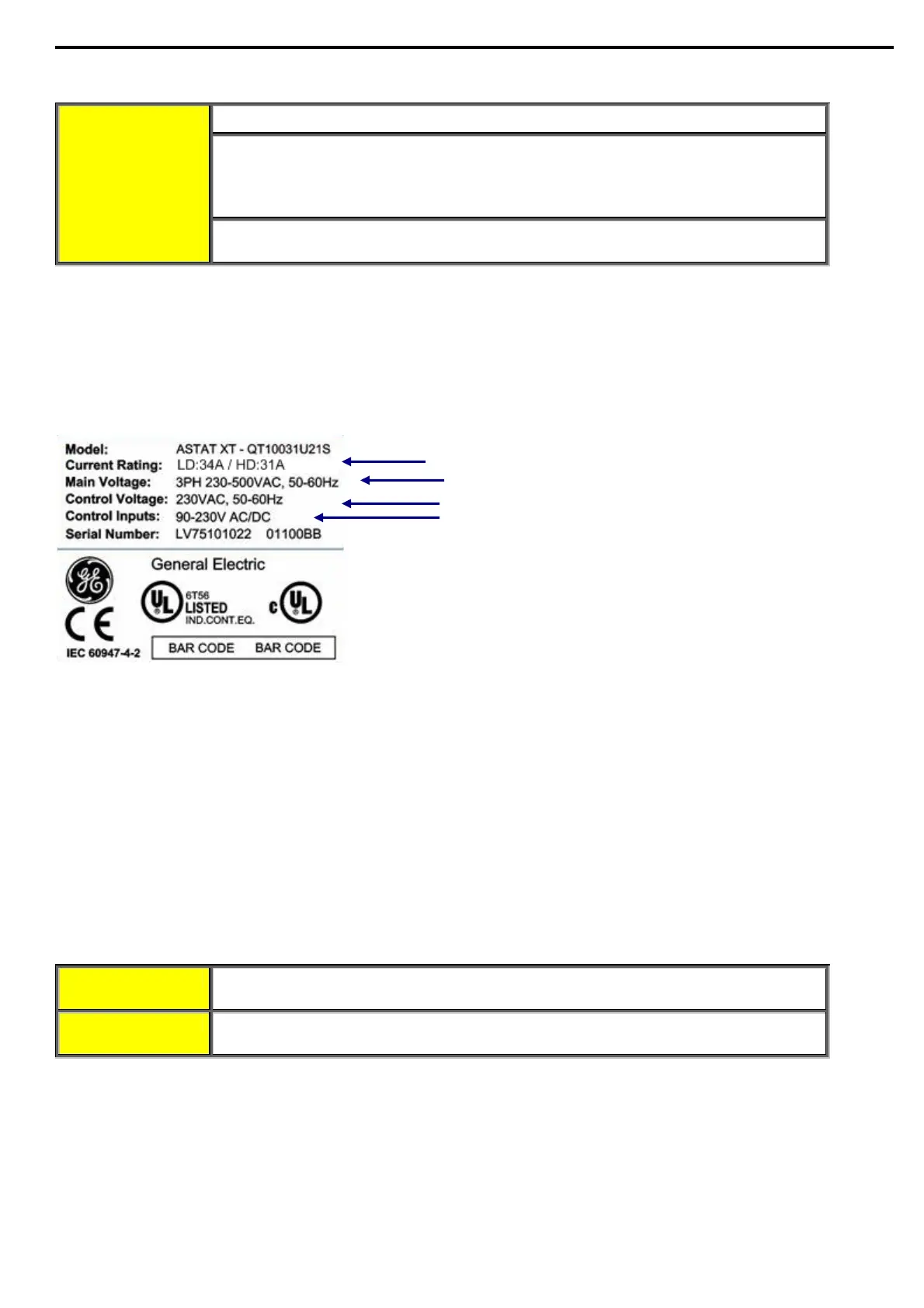
Also verify that the mains voltage, Control Voltage and Control Input voltage are as indicated on the name plate of
the ASTAT-XT.
Verify that motor current and load duty (LD or HD)
matches the Current Rating indication.
Verify mains voltage is correct!
Verify that Control Voltage (terminals L, N) is correct!
Verify that Control Input voltage (terminals 4-9) is correct!
ASTAT-XT name plate - example
5.2 Mounting
The ASTAT-X
T must be mounted vertically. Allow sufficient space for suitable airflow above and below the ASTAT-XT.
To improve heat dissipation, it is recommended that you mount the ASTAT-XT directly on the rear metal plate.
Notes:
(8) Do not mount the ASTAT-XT near heat sources.
(9) Surrounding air temperature in the cabinet should not exceed 50°C
(10) Protect the ASTAT-XT from dust and corrosive atmospheres.
5.3 Temperature Range & Heat Dissipation
The ASTAT-X
T is rated to operate within a temperature range of -10°C (14°F) to + 50°C (122°F).
Relative non-condensed humidity inside the enclosure must not exceed 95%.
ATTENTION Operating the ASTAT-XT with a surrounding air temperature that is higher than
40ºC and up to 50°C, derate the current by 2.5% for each °C that is above 40°C.
CAUTION Operating the ASTAT-XT with a surrounding air temperature that is higher than
60ºC may cause damage to the ASTAT-XT.
Heat dissipation from the ASTAT-XT is calculated as:
Ploss=3x1.3xI+FAN loss
where:
I represents motor current. Note that the motor current during the start process is higher than the motor rated
current.
FAN loss represents power loss caused by all internal fans (refer to section
3 page 11 for fan loss per model).
For example, during start of a 820A motor when Current Limit is set to 400%, heat dissipation can be
calculated as:
Ploss=3x1.3x4x820+150=12,792Watt≈12.8kW

 Loading...


