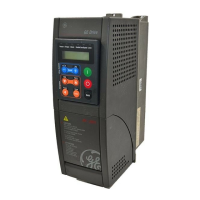
AV-300i Version 2 User’s Guide
—————— TABLE OF CONTENTS ——————
11
List of Figures
Figure 1.3.2.8.1: Braking Unit Function ..............................................................................................................38
Figure 1.4.5.2.1: Output Current (Reaction Time @ 3ms) Displaying ................................................................. 54
Figure 1.4.5.2.2: Optimal Output Current (Reaction Time @ 1ms) Displaying ...................................................55
Figure 1.4.5.3.1: Flux Reference (CH1) and Flux (CH2) Displaying ....................................................................56
Figure 1.4.5.3.2: Flux Reference (CH1) and Tuning of Flux (CH2) Displaying ....................................................56
Figure 1.4.5.3.3: Flux Reference (CH1) and Tuning of Magn Current Reference (CH2) Displaying ...................57
Figure 1.4.5.3.4: Flux Reference (CH1) and Magn Current Reference, with Overshoots, (CH2) Displaying ......57
Figure 1.4.5.4.1: Speed Ref1 (CH1) and Norm Speed (CH2) Displaying ............................................................58
Figure 1.4.5.4.2: Speed Ref1(CH1) and Norm Speed (CH2), with Overshoot, Displaying..................................58
Figure 1.7.2.1: Acceleration and Deceleration Ramps ........................................................................................87
Figure 1.7.3.1: Ramp Shape ................................................................................................................................89
Figure 1.11.2.1: Power Loss Control Function ..................................................................................................122
Figure 1.11.2.2: Power Loss Stop .................................................................................................................... 123
Figure 1.15.7.1: Diameter Calculation ............................................................................................................... 153
Figure 1.16.1.1: Control of Nip Rolls with Dancer ...........................................................................................155
Figure 1.16.2.1: Control of Nip Rolls with Loading Cell .................................................................................... 157
Figura 1.16.3.1: Control of Winders/Unwinders with Dancer ........................................................................... 160
Figure 1.16.4.1: Outlining of the Dancer Constant Measurement .................................................................... 163
Figure 1.16.5.1: Winder/Unwinder Control with Diameter Sensor .................................................................. 164
Figure 1.16.5.2: Relationship Between the Transducer Signal and the Winder Diameter .............................. 165
Figure 1.16.6.1: Pressure Control for Pumps and Extruders............................................................................. 166
Figure 1.16.8.1: Example with a Small and Big Diameter .................................................................................169
Figure 1.16.8.2: PI I Gain PID and PI I Output PID ratio ................................................................................. 170
List of Tables
Table 1.3.3.1: Recipe “Appl Function” ................................................................................................................ 40
Table 1.3.3.2: Recipe “Ramp & Speed Config” ...................................................................................................41
Table 1.3.3.3: Recipe “Appl Card & Comm” ........................................................................................................42
Table 1.3.3.4: Recipe”I/O Config” ....................................................................................................................... 43
Table 1.5.3.1-1: Setup for Control from Keyboard (Factory Setup) .....................................................................63
Table 1.5.3.2-1: Example Setup for Pushbutton Control ......................................................................................63
Table 1.5.3.3-1: Example Setup for LAN Control with Wired Fast Stop..............................................................64
Table 1.5.3.4-1: Example Setup for Unmanned Installation ................................................................................65
Table 1.12.1: Alarm List ..................................................................................................................................... 130
Table 1.12.8.1: Fault Pin List ............................................................................................................................. 131

 Loading...