B30 Patient Monitor
1-26
Document no. 2044677-001
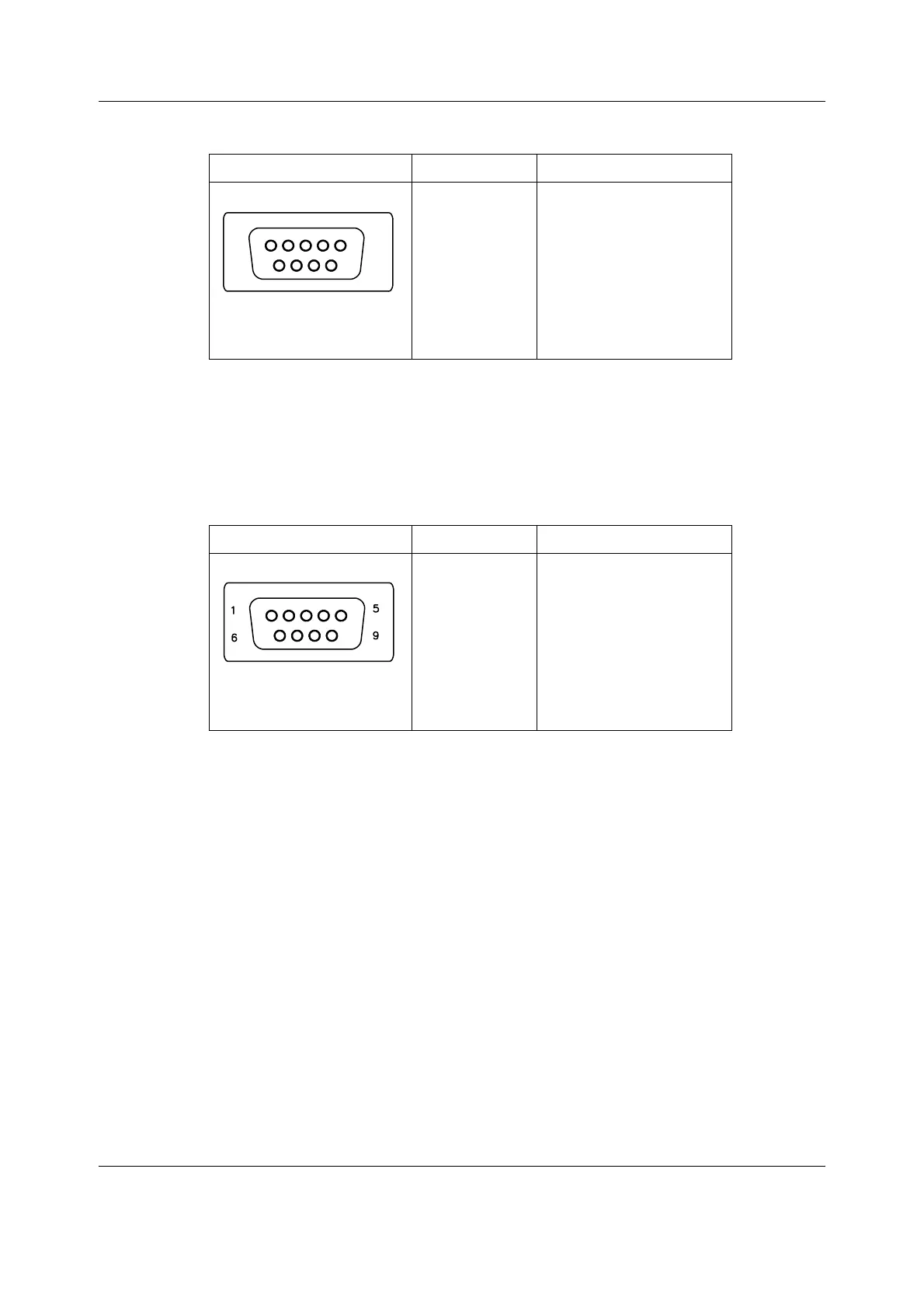
Net ID connector X8
Nurse Call (pin 8)
The nurse call signal is generated by the red and yellow alarms. When activated, the signal is
set to the high state and remains at the high state until the alarm situation is over or the
SILENCE ALARM key is pressed. The high state range is from 3.5 to 5 V, while the low state
range is from 0 to 0.5 V.
Serial port X9
9 pin female connector Pin Signal
1
2
3
4
5
6
7
8
9
NET_ID_CS TTL out
NET_ID_CLK TTL out
NET_ID_DO TTL out
NET_ID_DI TTL input
GND
+4.75 to +5.25V_out
GND (Reserved)
Nurse call, CMOS output
GND
9 pin male connector Pin Signal
1
2
3
4
5
6
7
8
9
GND
RXD, RS-232 input
TXD, RS-232 output
+4.75 to +5.25V
GND
N/C
RTS#, RS-232 output
CTS#, RS-232 input
N/C
1
5
6
9

 Loading...


