B30 Patient Monitor
1-38
Document no. 2044677-001
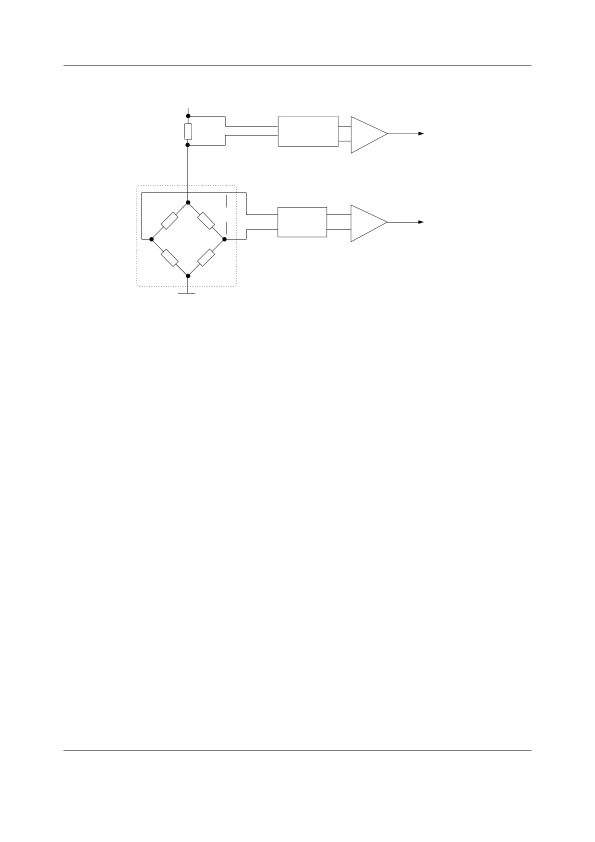
Figure 22 Pressure measurement principle
Pulse oximetry measurement section
LED control signals
The D/A converters of the microcontroller on the STP board set the LED intensity adjustment
values for the infrared and red LEDs of the SpO
2
probe. The microcontroller on the STP board
switches ON (to the adjusted intensity) and OFF the SpO
2
probe LEDs according to the
predetermined sequence.
LED driving circuit
Differential amplifiers measure the LED currents (LED current indication) of the SpO
2
probe over
the shunt resistors placed in the LED current paths. The LED driving voltages (LED voltage
indication) are measured from the driver circuitry. The LED driving circuits also have MOSFET
transistor matrix to enable the use of different probe configurations.
Measured signal preamplification
The preamplifier is a bipolar/single-ended current-to-voltage converter with adjustable gain. A
higher gain is used for measuring thin tissue. The preamplification stage has also ambient light
reduction and a second amplifier stage.
Input filter
Instrumentation
amplifier
to AD converter
Vout
G
PSM_pressure_meas_principle.vsd
Current
measurement
G
to AD converter
Vin
Pressure
transducer

 Loading...


