E-PSM(P)W module introduction
1-39
Document no. 2044677-001
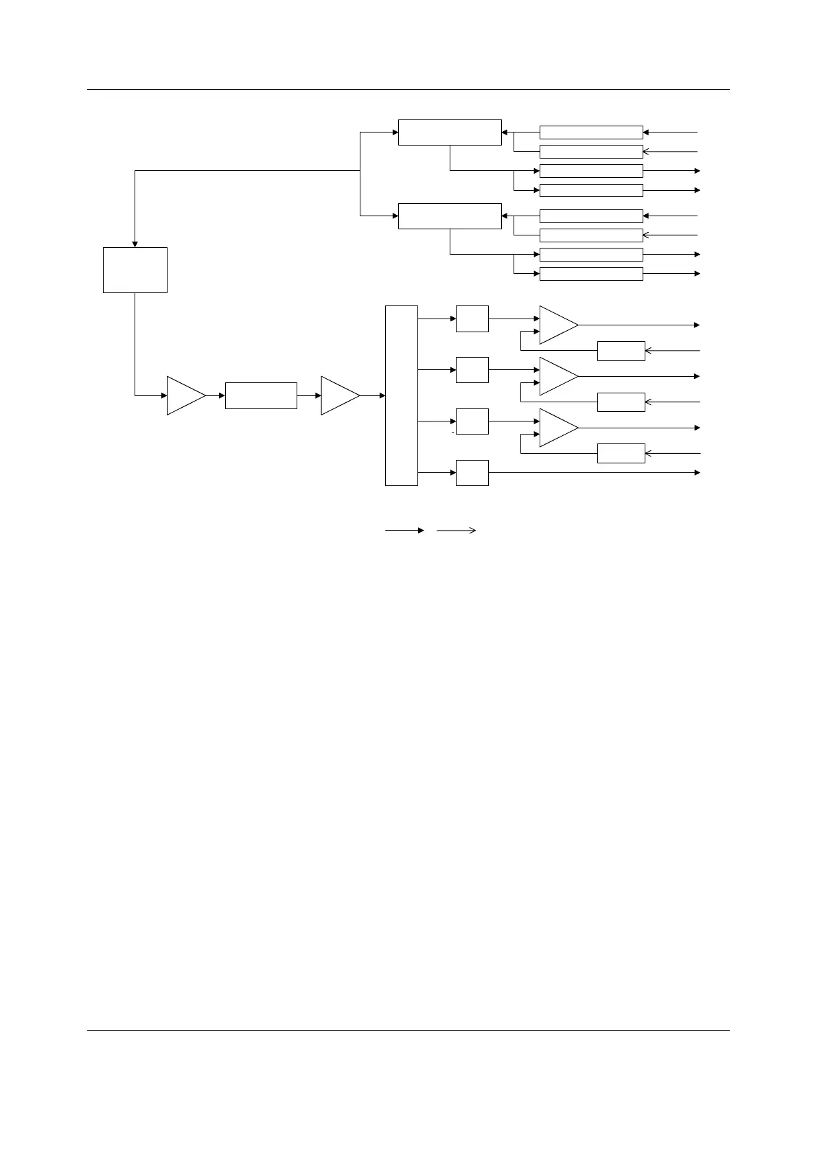
Figure 23 Pulse oximetry measurement block diagram
Red and infrared channel separation
It is possible to multiplex the detector signal to four different channels depending on the
content of the signal. The detector signal must at least multiplex into infrared and red signals.
Other channels are e.g. for diagnostic purposes.
Serial communication
An RS485 type bus driver makes the serial communication between the module and the frame.
The data transmission rate is 500kbps.
LED Intensity adjustment 1
LED Intensity adjustment 2
LED ON/OFF control 1
LED ON/OFF control 2
LED Driving circuit 1
LED Driving circuit 2
LED voltage indication 1
LED current indication 1
LED voltage indication 2
LED current indication 2
Preamplifier:
Current-to-voltage type
Bipolar/single-ended modes
Adjustable gain
Ambient reduction
Amplifier:
Gain = 2
DE-MUX
LP
LP
LP
LP
Gain=7.5
Gain=7.5
Gain=7.5
Amplifiers
DC-
suppression
DC-
suppression
DC-
suppression
Oximeter channel 1
Oximeter channel 2
Oximeter channel 3
Oximeter channel 4
SpO2
Probe
Analog Digital
Spo2_measurement_blck_diagr.vsd

 Loading...


