10 M1110150 006 © 2007 by General Electric Company. All rights reserved.
Chapter 4: Troubleshooting
Symptom Troubleshooting Steps
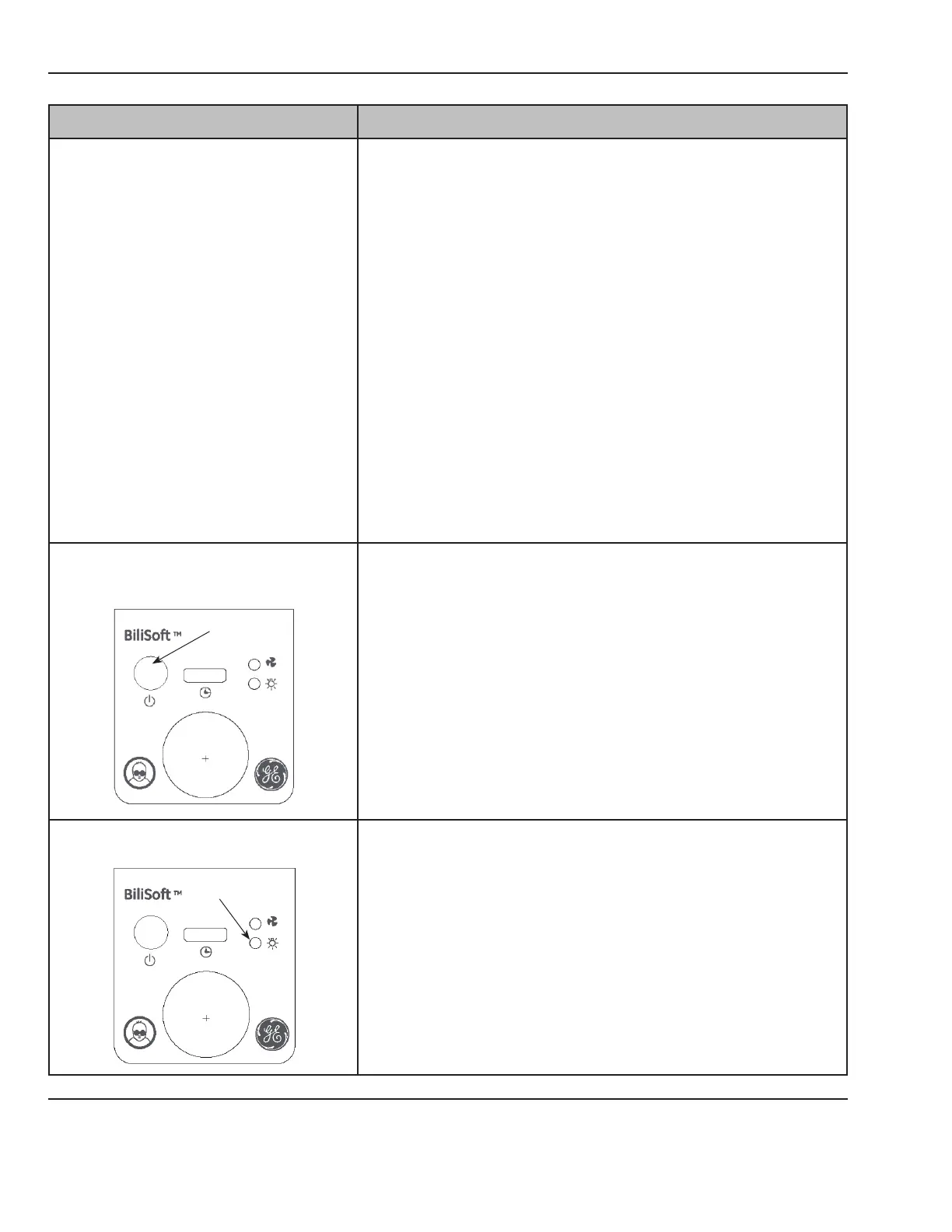
B No light output.
1. Check power connections and that the standby switch is on.
Check that the beroptic pad connector is fully inserted.
2. Check that the green power indicator on the standby switch is
lit. If indicator is not lit, see C.
3. Check if the Unit Overheated indicator is lit. If it is on, see A.
4. Check if the LED failure indicator is blinking. If it is blinking,
see D.
5. Check if the fan is running. If so, replace the Control PCB. If
not, remove cover and check Control PCB connections.
6. Disconnect J5 and check continuity through the beroptic
pad connector switch (pins 1 and 2) with the beroptic pad
connector inserted. If there is continuity, replace the Control
PCB. If there is no continuity, replace the beroptic pad
connector switch.
C Standby switch is on, but green indicator
does not light.
green o
1. Check that the power cord is in good condition, and properly
connected at both the light source and the line power source.
2. Check the fuses. Replace, if necessary.
3. Remove the cover and check the AC input to the Power Supply
at connector J1. If there is no AC voltage present, replace the
EMI lter or the AC harness as needed.
4. Check the 12V DC output of the Power Supply at connector J3
(pins 1 and 4). If there is no output, replace the Power Supply.
if there is output, replace the power supply harness or Control
PCB as needed.
D LED failure indicator light is blinking.
blinking
1. Remove cover and check the Control PCB and LED PCB
connections.
2. Check the voltage (5V is typical, but varies with array current
demand) at pin 1 on U2 on the Control PCB and ground on pin
4 on J2 on the Power Supply. Repeat on U8 and U11 on the
main control board. If voltage is present at all 3 test points,
replace the LED module. If not, replace the Control PCB.