4-42 D30 LINE DISTANCE PROTECTION SYSTEM – INSTRUCTION MANUAL
FRONT PANEL INTERFACE CHAPTER 4: INTERFACES
4
Figure 4-50: LED panel 2 (default labels)
4.2.4.3 Graphical front panel
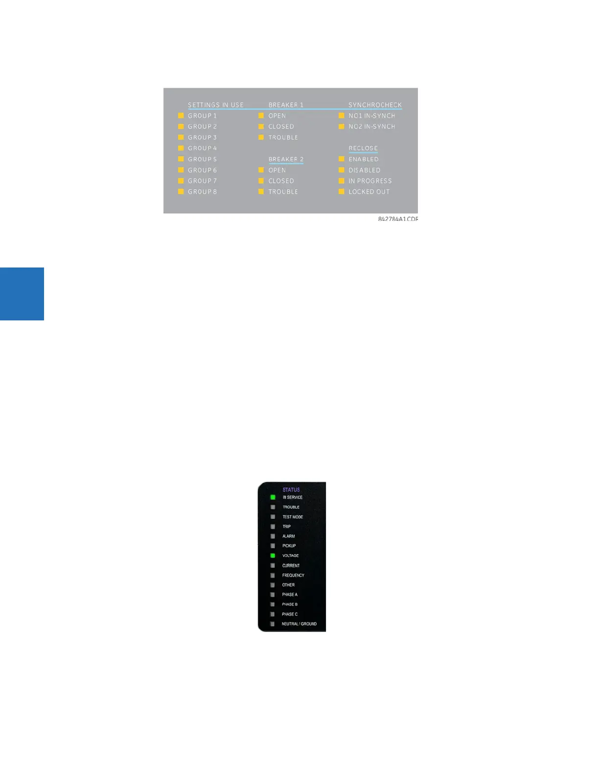
The graphical front panel has 14 LEDs. LEDs 1 to 5 are fixed status LEDs, and LEDs 6 to 14 are programmable.
Status indicators
• IN SERVICE — Indicates that control power is applied, all monitored inputs/outputs and internal systems are fine, the
relay’s test mode is disabled, and the relay is in (online) Programmed mode (under Settings > Product Setup >
Installation)
• TROUBLE — Indicates that the relay has detected an internal problem. Check the self-test messages outlined at the
end of the Commands and Targets chapter, and view the event records under Actual Values > Records. For a beta /
pre-release, this LED is always on.
• TEST MODE — Indicates that the relay is in Isolated (solid) or Forcible (flashing) test mode. For information, see the Test
Mode section in the Settings chapter.
• TRIP — Indicates that the selected FlexLogic operand serving as a trip input has operated. Set the operand under
Settings > Product Setup > User-Programmable LEDs > Trip & Alarm LEDs. This indicator latches; initiate the reset
command to reset the latch.
• ALARM — Indicates that the selected FlexLogic operand serving as an alarm input has operated. Set the operand
under Settings > Product Setup > User-Programmable LEDs > Trip & Alarm LEDs.
Figure 4-51: Example of LEDs on graphical front panel