CHAPTER 5: SETTINGS CONTROL ELEMENTS
D30 LINE DISTANCE PROTECTION SYSTEM – INSTRUCTION MANUAL 5-259
5
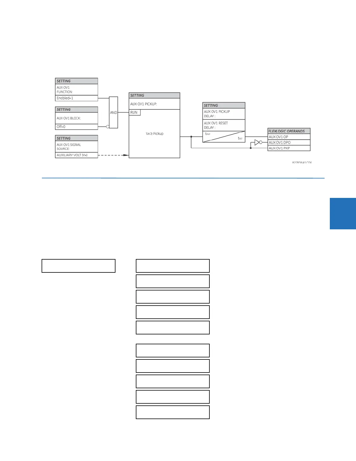
A typical application for this element is monitoring the zero-sequence voltage (3V_0) supplied from an open-corner-delta
VT connection.
Figure 5-147: Auxiliary overvoltage logic
5.8 Control elements
5.8.1 Overview
Control elements are used for control rather than protection. See the Introduction to Elements section at the beginning of
this chapter for information.
5.8.2 Trip bus
SETTINGS CONTROL ELEMENTS TRIP BUS TRIP BUS 1(6)
TRIP BUS 1
TRIP BUS 1
FUNCTION: Disabled
Range: Enabled, Disabled
TRIP BUS 1 BLOCK:
Off
Range: FlexLogic operand
TRIP BUS 1 PICKUP
DELAY: 0.00 s
Range: 0.00 to 600.00 s in steps of 0.01
TRIP BUS 1 RESET
DELAY: 0.00 s
Range: 0.00 to 600.00 s in steps of 0.01
TRIP BUS 1 INPUT 1:
Off
Range: FlexLogic operand
TRIP BUS 1 INPUT 16:
Off
Range: FlexLogic operand
TRIP BUS 1
LATCHING: Disabled
Range: Enabled, Disabled
TRIP BUS 1 RESET:
Off
Range: FlexLogic operand
TRIP BUS 1:
TARGET: Self-reset
Range: Self-reset, Latched, Disabled
TRIP BUS 1
EVENTS: Disabled
Range: Enabled, Disabled