CHAPTER 9: THEORY OF OPERATION GROUND DIRECTIONAL OVERCURRENT
D30 LINE DISTANCE PROTECTION SYSTEM – INSTRUCTION MANUAL 9-17
9
See the Application of Settings chapter for information on setting calculations.
9.3 Ground directional overcurrent
9.3.1 Description
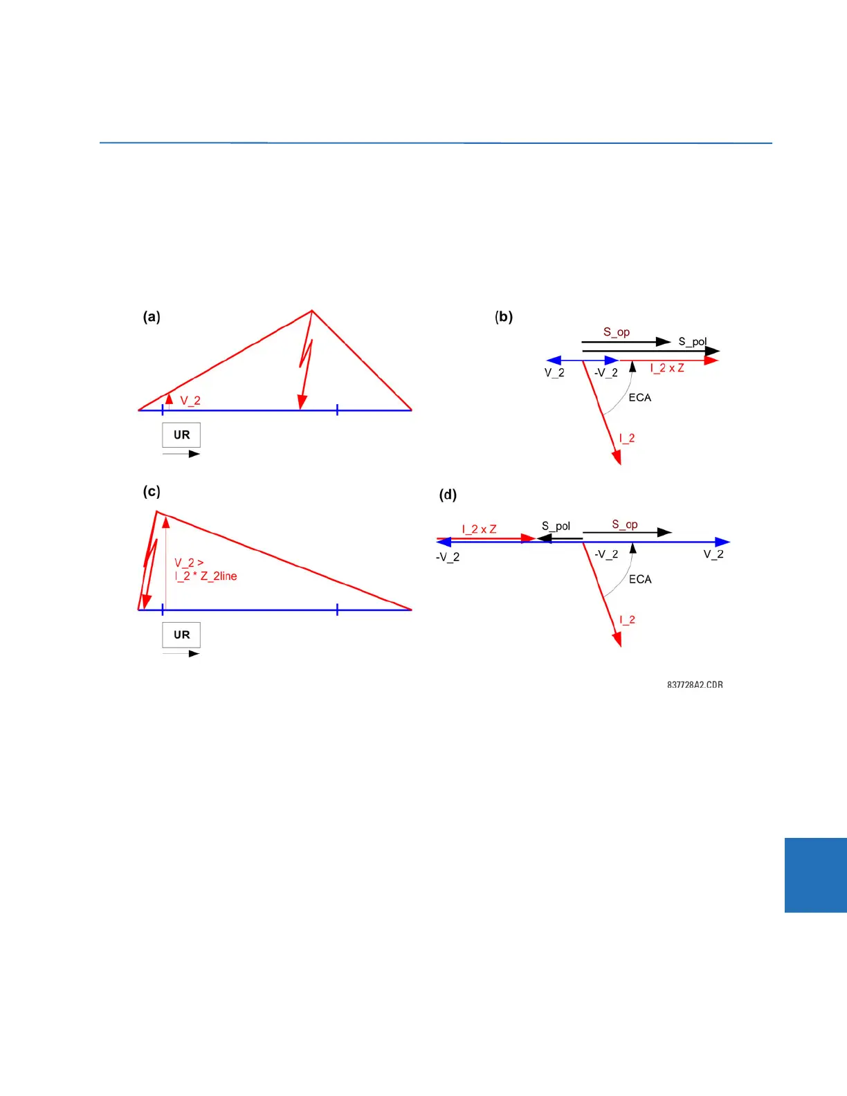
Consider the negative-sequence directional overcurrent element. As shown, the negative-sequence voltage can be low
during internal fault conditions.
Figure 9-6: Offset impedance augmentation
In order to ensure operation of the element under such circumstances, the angle comparator uses a polarizing voltage
augmented by the negative-sequence current as per following equations:
Forward-looking element:
S_pol = -V_2 + I_2 x Z_offset x 1∠ECA
S_op = I_2 x 1∠ECA Eq. 9-8
Reverse-looking element:
S_pol = -V_2 + I_2 x Z_offset x 1∠ECA
S_op = -I_2 x 1∠ECA Eq. 9-9
Where ECA = forward ECA angle (maximum torque angle) and Z_offset = offset impedance. The effect of the augmentation
for forward and reverse fault is shown in the previous figure. As long as the offset impedance is not higher than the
negative-sequence line impedance, the element ensures correct and fast fault direction identification for both forward and
reverse faults. The same principle applies to the neutral directional overcurrent element.