9-16 D30 LINE DISTANCE PROTECTION SYSTEM – INSTRUCTION MANUAL
PHASE DISTANCE APPLIED TO POWER TRANSFORMERS CHAPTER 9: THEORY OF OPERATION
9
If installed at the location X, the relay uses the following input signals for its phase AB distance element:
V = V
AB
= 77.402 kV ∠57.5° primary or 29.49 V ∠57.5° secondary
I = I
A
– I
B
= 2.576 kA ∠–27.6° primary or 42.93 A ∠–27.6° secondary
And consequently it sees an apparent impedance of
Z
app
= V / I = 30.05 Ω ∠85° primary or 0.687 Ω ∠85° secondary
If applied at location H, the relay sees the following input signals:
Table 9-11: Relay input signals at location H
The relay is set as follows:
XFMR VOL CONNECTION = “Dy11”
XFMR CUR CONNECTION = “Dy11”
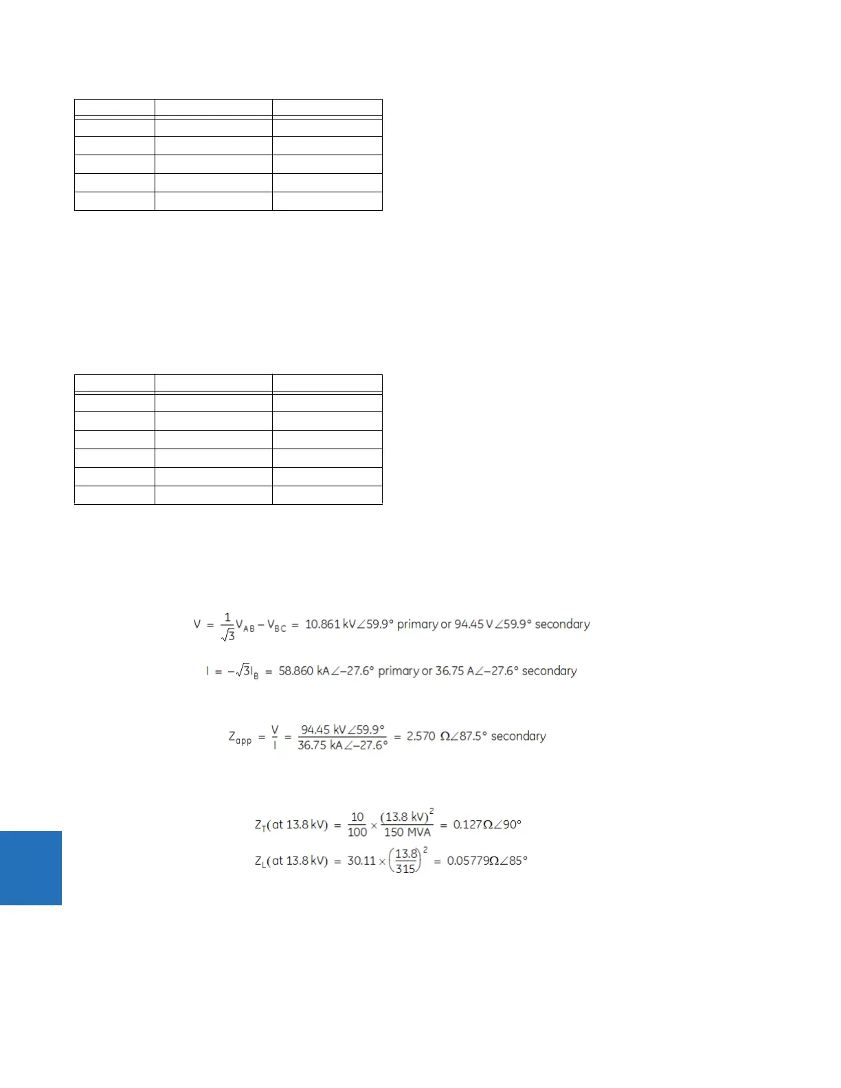
Consequently, the following signals are applied to the phase AB distance element:
Eq. 9-4
Eq. 9-5
This results in the following apparent impedance:
Eq. 9-6
This value is a correct measure of the distance from the VT location to the fault. For relay location 2, this certainly includes
the positive-sequence impedance of the transformer:
Eq. 9-7
Thus, 0.127 Ω ∠90° + 0.05779 Ω ∠85° = 0.1847 Ω ∠88.4° primary side or 2.569 Ω ∠88.4° on the secondary side.
This example illustrates how the relay maintains correct reach for fault behind power transformers. When installed at X,
the relay needs to be set to 0.687 Ω ∠85° secondary in order to reach to the fault shown in the figure. When installed at H,
the relay needs to be set to 2.569 Ω ∠88.4° to ensure exactly same coverage.
VB 97.23 kV ∠–53.4° 37.04 V ∠–53.4°
VC 181.8 kV ∠–150.0° 69.26 V ∠–150.0°
IA 1.288 kA ∠–27.6° 21.47 A ∠–27.6°
IB 1.288 kA ∠152.4° 21.47 A ∠152.4°
IC 0 0
Input Primary Secondary
VA 7.584 kV ∠–5.59° 69.95 V ∠–5.59°
VB 6.269 kV ∠–120.1° 54.52 V ∠–120.1°
VC 7.751 kV ∠125.5° 65.84 V ∠125.5°
IA 16.976 kA ∠–27.6° 10.61 A ∠–27.6°
IB 33.952 kA ∠152.4° 21.22 A ∠152.4°
IC 16.976 kA ∠–27.6° 10.61 A ∠–27.6°
Input Primary Secondary