CHAPTER 8: APPLICATION OF SETTINGS PHASE DISTANCE THROUGH POWER TRANSFORMERS
D30 LINE DISTANCE PROTECTION SYSTEM – INSTRUCTION MANUAL 8-9
8
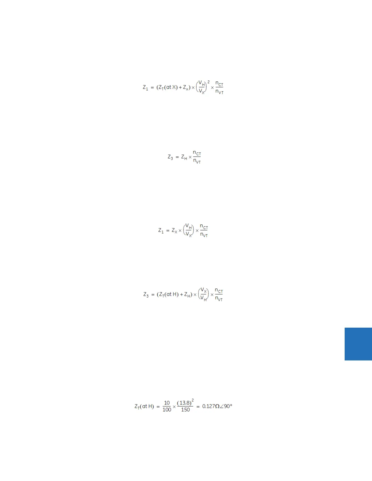
8.4.1.2 Zone 1 setting in application A
As the transformer is located between the potential source and the reach point for Zone 1, the reach impedance must
include the positive-sequence impedance of the transformer. In addition, the primary impedance must be re-calculated for
the voltage level of the VTs and CTs, and eventually, re-calculated to secondary quantities:
Eq. 8-4
8.4.1.3 Zone 3 setting in application A
As the transformer is not located between the potential source and the reach point for Zone 3, the reach impedance must
not include the positive-sequence impedance of the transformer. Because both VTs and CTs are located on the same side
as the intended reach point, no correction for the transformer ratio is required. The primary impedance must be only re-
calculated to secondary quantities:
Eq. 8-5
8.4.1.4 Zone 1 setting in application B
As the transformer is not located between the potential source and the reach point for Z1, the reach impedance must not
include the positive-sequence impedance of the transformer. The CTs are located on the other side of the transformer, thus
transformer ratio must be included:
Eq. 8-6
8.4.1.5 Zone 3 setting in application B
As the transformer is located between the potential source and the reach point for Zone 3, the reach impedance must
include the positive-sequence impedance of the transformer. The VTs are located on the other side of the transformer, thus
transformer ratio must be included:
Eq. 8-7
8.4.2 Example
Given the following for the system shown in the previous section:
Z
X
= 30 Ω ∠85° (intended reach of Zone 1)
Z
H
= 0.06 Ω ∠88° (intended reach of Zone 3)
n
CT
= 8000:5 = 1600 (located at H)
n
VT
= 315000:120 = 2625 (located at X)
Transformer: 13.8/315 kV, 150 MVA, 10%, delta/wye, 315 kV side lagging 30°
Transformer impedance:
Eq. 8-8