4-44 D30 LINE DISTANCE PROTECTION SYSTEM – INSTRUCTION MANUAL
FRONT PANEL INTERFACE CHAPTER 4: INTERFACES
4
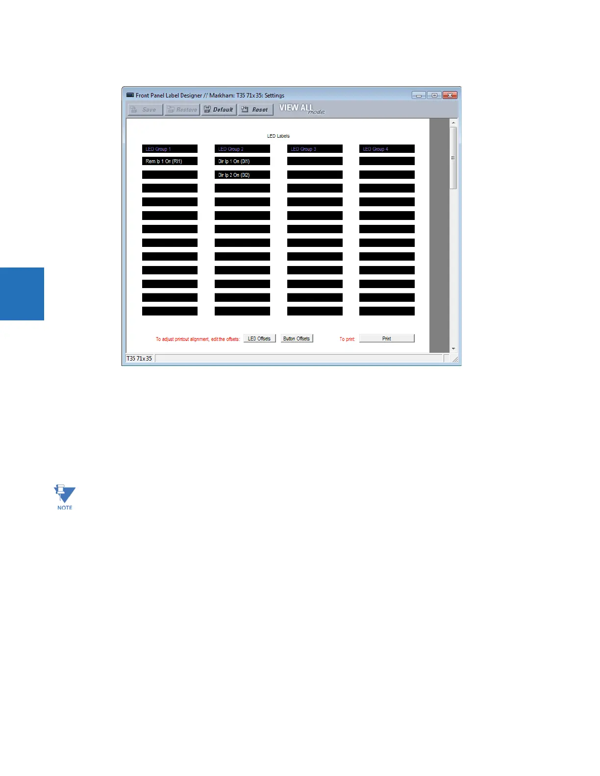
Figure 4-52: Enhanced front panel label designer
4. Enter the text to appear next to each LED and above each user-programmable pushbutton in the fields provided. The
LED Offsets and Button Offsets buttons move all labels left/right and up/down on the page (they both do the same
action, so use either button). The Button Offsets button does not display when there are no pushbuttons to customize.
5. Feed the UR front panel label cutout sheet into a printer and press the Print button in the front panel report window.
6. When printing is complete, fold the sheet along the perforated lines and punch out the labels.
7. Remove the UR label insert tool from the package and bend the tabs as described in the following procedures. These
tabs are used for removal of the default and custom LED labels.
The label package shipped with every D30 contains the three default labels, the custom label template sheet, and the label
removal tool.
If the default labels are suitable for your application, insert them in the appropriate slots and program the LEDs to match
them. If you require custom labels, use the following procedures to remove the original labels and insert the new ones.
Use the tool with the printed side containing the GE part number facing the user.