CHAPTER 2: PRODUCT DESCRIPTION SPECIFICATIONS
D30 LINE DISTANCE PROTECTION SYSTEM – INSTRUCTION MANUAL 2-19
2
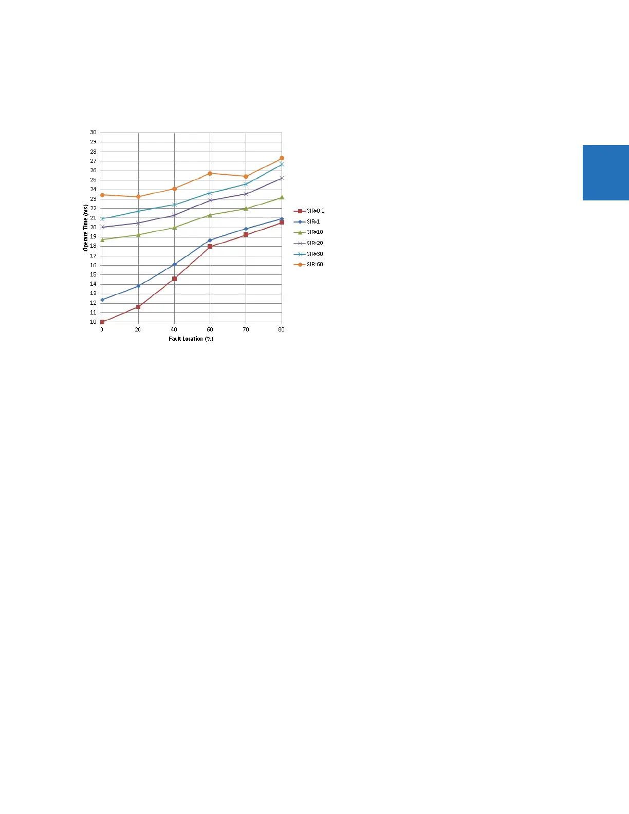
PHASE DISTANCE OPERATING TIME CURVES
The operating times are response times of a microprocessor part of the relay. See output contacts specifications for estimation of the
total response time for a particular application. The operating times are average times including variables such as fault inception angle
or type of a voltage source (magnetic VTs and CVTs). The figure shows zone 1 distance time curves for a 60 Hz system at nominal system
frequency.
GROUND DISTANCE
Characteristic: Mho (memory polarized or offset) or Quad (memory polarized or non-directional), selectable indi-
vidually per zone
Reactance polarization: negative-sequence or zero-sequence current
Non-homogeneity angle: –40 to 40° in steps of 1
Number of zones: 5
Directionality: forward, reverse, or non-directional per zone
Reach (secondary Ω): 0.02 to 500.00 Ω in steps of 0.01
Reach accuracy:
Zone 1: ±5% including the effect of CVT transients up to an SIR of 30 and ±7% for 30<SIR< 60 at RCA
angle
Zones 2 to 5: ±5% for steady fault conditions
Distance characteristic angle: 30 to 90° in steps of 1
Distance comparator limit angle: 30 to 90° in steps of 1
Directional supervision:
Characteristic angle: 30 to 90° in steps of 1
Limit angle: 30 to 90° in steps of 1
Zero-sequence compensation
Z0/Z1 magnitude: 0.00 to 10.00 in steps of 0.01
Z0/Z1 angle: –90 to 90° in steps of 1
Zero-sequence mutual compensation
Z0M/Z1 magnitude: 0.00 to 7.00 in steps of 0.01
Z0M/Z1 angle: –90 to 90° in steps of 1
Right blinder (Quad only):
Reach: 0.02 to 500 Ω in steps of 0.01
Characteristic angle: 60 to 90° in steps of 1
Left blinder (Quad only):
Reach: 0.02 to 500 Ω in steps of 0.01
Characteristic angle: 60 to 90° in steps of 1
Time delay: 0.000 to 65.535 s in steps of 0.001
Timer accuracy: ±3% of operate time or ±1/4 cycle (whichever is greater)
Current supervision: