5-134 D30 LINE DISTANCE PROTECTION SYSTEM – INSTRUCTION MANUAL
PRODUCT SETUP CHAPTER 5: SETTINGS
5
If the direct input and output scheme is configured to operate in a ring (DIRECT I/O CH1 RING CONFIGURATION or DIRECT I/O
CH2 RING CONFIGURATION
is “Yes”), all direct output messages are received back. If not, the direct input/output ring break
self-test is triggered. The self-test error is signaled by the DIRECT RING BREAK FlexLogic operand.
Select the DIRECT I/O DATA RATE to match the data capabilities of the communications channel. All IEDs communicating
over direct inputs and outputs must be set to the same data rate. UR-series IEDs equipped with dual-channel
communications cards apply the same data rate to both channels. Delivery time for direct input and output messages is
approximately 0.2 of a power system cycle at 128 kbps and 0.4 of a power system cycle at 64 kbps, per each "bridge."
Table 5-17: Direct input and output data rates
The
DIRECT I/O CHANNEL CROSSOVER setting applies to a D30 with dual-channel communication cards and allows crossing
over messages from channel 1 to channel 2. This places all UR-series IEDs into one direct input and output network
regardless of the physical media of the two communication channels.
The following application examples illustrate the basic concepts for direct input and output configuration. See the Inputs
and Outputs section in this chapter for information on configuring FlexLogic operands (flags, bits) to be exchanged.
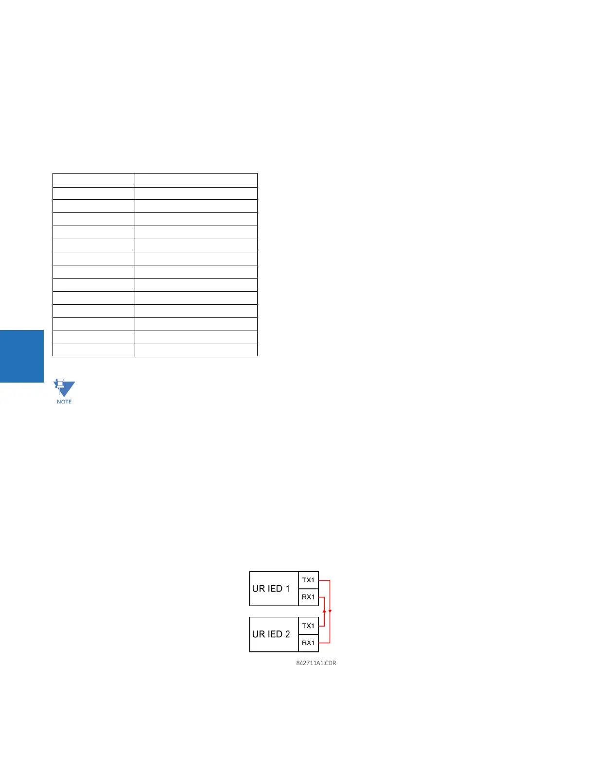
Example 1: Extending the input/output capabilities of a UR-series relay
Consider an application that requires additional quantities of contact inputs or output contacts or lines of programmable
logic that exceed the capabilities of a single UR-series chassis. The problem is solved by adding an extra UR-series IED,
such as the C30, to satisfy the additional input and output and programmable logic requirements. The two IEDs are
connected via single-channel digital communication cards as shown in the figure.
Figure 5-59: Input and output extension via direct inputs and outputs
In this application, apply the following settings. For UR-series IED 1:
Module Supported data rates
2A, 2B 64 kbps
2E, 2F 64 kbps
2G, 2H 128 kbps
2I, 2J 64 kbps, 128 kbps
72, 73 64 kbps, 128 kbps
74, 75 64 kbps
76, 77 64 kbps
7A, 7B, 7C, 7D 64 kbps, 128 kbps
7E, 7F, 7G 64 kbps
7H, 7I, 7J, 7K 64 kbps, 128 kbps
7L, 7M, 7N, 7P, 7Q 64 kbps
7R, 7S 64 kbps
7T, 7W 64 kbps
The G.703 modules are fixed at 64 kbps. The DIRECT I/O DATA RATE setting is not applicable to these modules.