Chapter 1. Installation
8 DigitalFlow™ Multipurpose Ultrasonic Liquid Flowmeter Startup Guide (1- and 2-Channel)
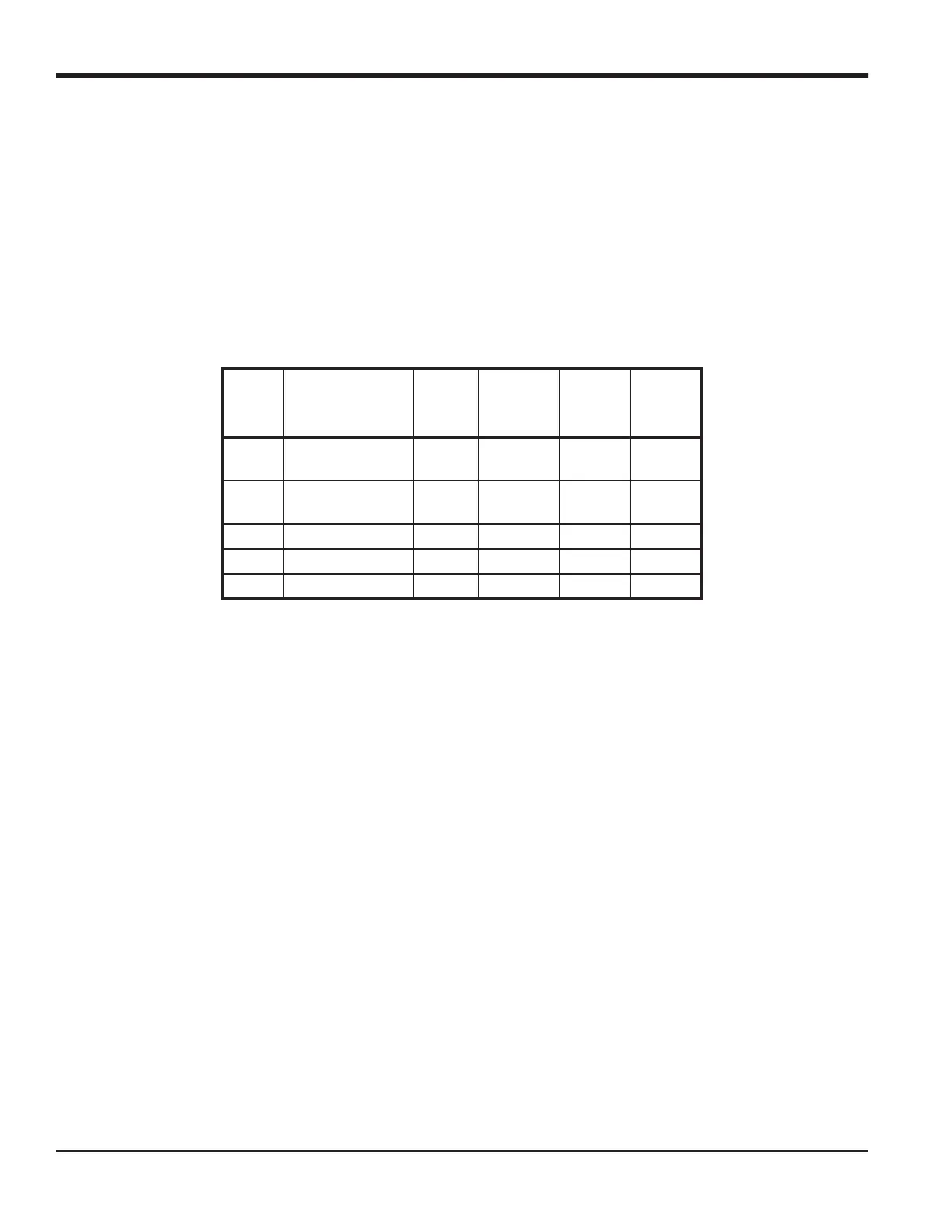
1.7.4a Wiring the RS232 Interface
Use the serial port to connect the Model DF868 flowmeter to a printer, an ANSI terminal or a personal computer. The
RS232 interface is wired as Data Terminal Equipment (DTE), and the signals available at terminal block J1 are shown
in Table 1. Refer to Figure 10 on page 16 and complete the following steps:
1. Disconnect the main power to the unit.
2. Install the required cable clamp in the chosen conduit hole on the side of the electronics enclosure.
3. Use the information in Table 1 to construct a suitable cable for connecting the Model DF868 to the external device.
If desired, an appropriate cable may be purchased from the factory.
Note: Signal names that imply direction (e.g., transmit and receive) are named from the point of view of the DTE
device (the GE meter is usually considered the DTE device). When the RS232 standard is strictly followed,
these signals are labeled with the same name and pin # on the DCE device side as well. Unfortunately, the
convention is not followed because the DTE and DCE side get confused. Therefore, connections that imply
direction are changed to reflect their direction on the DCE side.
4. Feed the flying leads end of the cable through the conduit hole and wire it to terminal block
J1. Connect the other
end of the cable to the printer, ANSI terminal or personal computer, and secure the cable clamp.
After the wiring has been completed, consult the User’s Manual for the external device to configure it for use with the
Model DF868.
1.7.4b Wiring the RS485 Interface
Use the optional RS485 serial port to network multiple DF868 flowmeters to a single computer terminal. Upon request,
the standard RS232 port on the DF868 may be configured as a two-wire, half-duplex RS485 interface, through a device
such as the INMAC Model 800052 RS232-RS422/RS485 converter.
IMPORTANT: The DF868 must be configured at the factory for RS485 operation.
To wire the RS485 serial port, refer to Figure 10 on page 16 and complete the following steps:
1. Disconnect the main power to the unit.
2. Install the required cable clamp in the chosen conduit hole on the side of the electronics enclosure.
Table 1: RS232 Connection to DCE or DTE Device
J1 Pin
Signal
Description
DCE
DB25
Pin #
DCE DB9
Pin #
DTE
DB25
Pin #
DTE
DB9
Pin #
5 DTR (Data
Terminal Ready)
20 4 20 4
6 CTS
(Clear to Send)
47 58
7 COM (Ground) 7 5 7 5
8 RX (Receive) 2 3 3 2
9 TX (Transmit) 3 2 2 3

 Loading...


