Chapter 2. Initial Setup
28 DigitalFlow™ Multipurpose Ultrasonic Liquid Flowmeter Startup Guide (1- and 2-Channel)
2.6.9 Reynolds Correction
11. Press [F1] to turn Reynolds Correction off, or [F2] to turn it on.
Note: Reynolds Correction is a number based on the Kinematic Viscosity and flow rate of the fluid. It should be
enabled for most applications.
12. When you enable the Reynolds Correction Factor, you must also enter the Kinematic Viscosity of your fluid, as
listed in Sound Speeds and Pipe Size Data. Use the numeric keys to enter a value, and press
[ENT].
2.6.10 Calibration Factor
13. Enter a value for the flow Calibration Factor and press [ENT]. The default value is 1.00, but values between 0.50
and 2.00 may be entered.
14. The menu now varies, depending on whether you have activated the TransFlection or Transit-Time mode.
• If you activated the TransFlection mode, the program asks for the Depth of Reflector. This setting determines where
in the pipe the DF868 looks for the reflected signal. The default value is 50%. Use the numeric keys to enter a
value, and press
[ENT].
Note: GE recommends activating the Reynolds Correction Factor when the Depth of Reflector is set at 50%. You can
disable the Reynolds Correction Factor when the Depth of Reflector is set at any other value.
• If you activated the Transit-Time mode, two steps appear.
a. Use the
[F1]-[F4] keys to select the desired Number of Traverses, the number of times the ultrasonic signal
traverses the pipe, from 1 to 5.
b. The Transducer Spacing prompt displays the spacing of the transducers, as calculated from the information you
have entered. Record this number and use it to properly space transducers.
Note: If necessary, you can overwrite the spacing shown (using the numeric keys) to match the actual physical
spacing of the transducers. The factory does not recommend overwriting the spacing. If you must, do not
change the spacing by more than ±10% from the value shown.
You have completed entering pipe parameters for clamp-on transducers. Press
[ENT] to return to the start of the PIPE
submenu, and [EXIT] to leave the submenu.
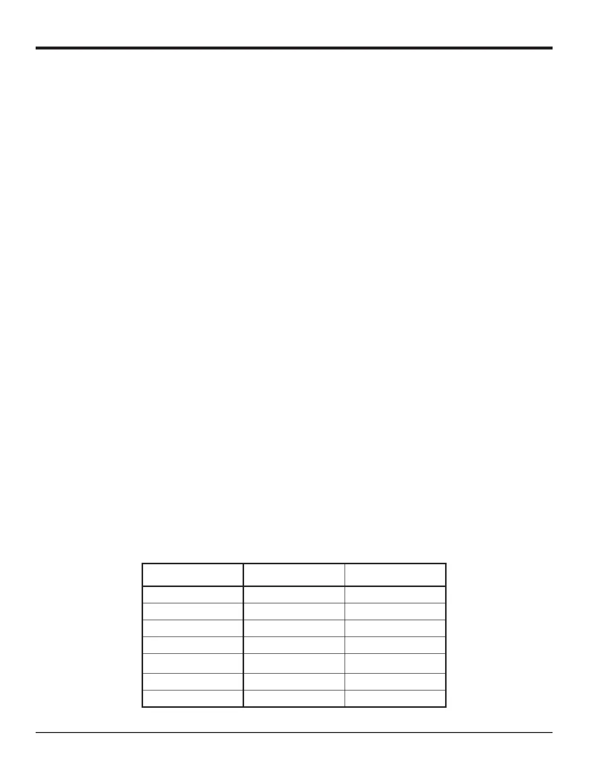
Table 12 lists the numeric parameters in the PIPE submenu, with their high and low limits.
Table 12: Low and High Limits for PIPE Parameters
Parameter Low Limit High Limit
Wedge Angle 25° 90°
Pipe OD 0.12 in. 300 in.
Pipe Wall 0 in. 4.0 in.
Lining Thickness 0 in. 4.0 in.
Kinematic Viscosity 0.1
10,000 (E-6 ft
2
/s)
Path Length 0.12 in. 480 in.
Axial Length 0.12 in. 480 in.

 Loading...


