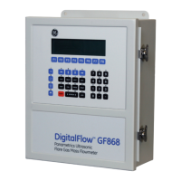
Do you have a question about the GE DigitalFlow XGM868i and is the answer not in the manual?
Defines types of notes: regular, important, and cautionary.
Covers general safety, auxiliary equipment safety, and working area hazards.
Details on qualified personnel, safety equipment, and environmental compliance.
Overview of installation and steps for unpacking the system.
Guidelines for selecting optimal locations for flowcell and enclosure.
Positioning the enclosure and flowcell for access and safety compliance.
Optimal placement for transducers and routing cables to avoid interference.
Mounting the flowcell and installing temperature/pressure transmitters.
Securing the weather-resistant enclosure using provided mounting bosses.
Detailed steps for wiring power, transducers, serial ports, and option cards.
Connecting the unit to power and connecting CH1/CH2 transducers.
Connecting for PC communication and wiring analog outputs.
Connecting various functional option cards like Alarms, RTD, MODBUS.
Overview of setup and available methods for configuration.
Navigating menus and entering data using the magnetic keypad.
Configuring system-wide parameters like units and pressure.
Choosing units for flow rate, time, and totalization displays.
Enabling measurement channels and selecting Skan/Measure techniques.
Entering channel labels, messages, units, and transducer/pipe data.
Inputting transducer numbers, frequencies, and pipe dimensions.
Overview of powering up and taking measurements.
Energizing the unit and initiating the startup sequence.
Interpreting and customizing displayed parameters on the LCD.
Connecting and viewing data via PanaView software.
Arranging and viewing multiple data screens simultaneously.
Procedures for obtaining flow rate data from the device.
Temporarily stopping measurements without powering down the unit.
Hardware configuration, environmental limits, and physical dimensions.
Velocity accuracy, range, rangeability, and repeatability.
Power supply, consumption, digital ports, and analog outputs.
Details on available analog inputs, RTD inputs, and other option cards.
Type, temperature range, pressure range, materials, and cable details.
Process connections, transducer connections, and pipe size/materials.
Requirements for CE Mark compliance for specific countries.
Specific cable types and grounding for CE compliance.
Table listing available option cards and their functions.
Table to document installed option cards and setup.
Template for recording all configured system and channel parameters.
Importance of path (P) and axial (L) dimensions for accuracy.
Methods for measuring P and L directly or calculating them.
| Brand | GE |
|---|---|
| Model | DigitalFlow XGM868i |
| Category | Measuring Instruments |
| Language | English |
