Chapter 1. Installation
4 DigitalFlow™ XGM868i Startup Guide
1.4 Installing a Flowcell
A flowcell is the section of pipe where the transducers are mounted. It can be created either by mounting the
transducers on the existing pipeline or by mounting them on a spoolpiece. A spoolpiece is a separately manufactured
pipe section, matched to the existing pipe, which contains ports for mounting the transducers. This approach allows the
transducers to be aligned and calibrated before inserting the spoolpiece into the pipeline.
Figure 1 on page 2 shows a typical Model XGM868i spoolpiece, with a mounting bracket to hold the electronics
enclosure. For detailed instructions on installing the transducers and/or spoolpiece, refer to the supplied drawings and
the enclosed GE Gas Transducer Installation Guide (916-049).
1.5 Installing Temperature and Pressure Transmitters
Optional temperature and pressure transmitters may be installed near the ultrasonic transducer ports as part of the
flowcell. Be sure to observe the siting requirements given earlier in this chapter. These transmitters should send a
0/4-20 mA signal to the Model XGM868i. In turn, the Model XGM868i must be fitted with a suitable option card to
process the signals and to provide the required 24 VDC power to the transmitters. Any desired transmitters or sensors
may be used, but they must have an accuracy equal to 0.5% of the reading or better.
Note: Resistive Thermal Devices (RTDs) are a good choice for measuring the temperature.
Typically, a 1/2” or 3/4” NPT female threaded port is used to mount the transmitters on the flowcell. If the pipeline is
insulated, the coupling may need to be extended to provide convenient access. Of course, other types of mounting
ports, including flanged ports, may be used for the transmitters.
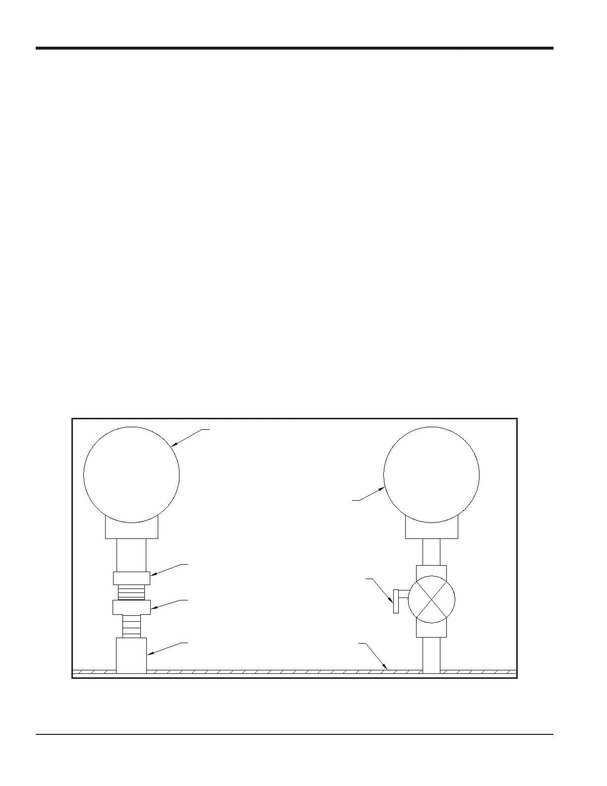
Figure 2 shows a typical mounting arrangement for the pressure and temperature transmitters. The temperature sensor
should protrude 1/4 to 1/2 way into the pipe.
Figure 2: Typical Temperature/Pressure Transmitter Mounting
Temperature Transmitter
RTD
Thermowell
Coupling
Pressure Transmitter
Isolation Valve
Flowcell Wall

 Loading...


