1.8 Power-Up
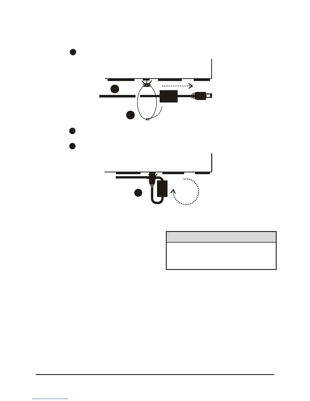
Use the diagram below to secure the power cord to the back panel.
2
1
3
Slide approximatel
6 inches of the power cord throu
h the pre-installe
cable tie (approximately 1 inch after the ferrite core).
Tighten the cable tie until the cord is secure. Do not over tighten.
Loop the power cord end around and insert into the power receptacle on
the back panel.
2
1
3
It is important that the power-up procedures be followed carefully. The unit uses its auto-detect
feature to detect camera signals during power-up, and configure itself automatically.
Power-up procedure
Power Supply Input
Once the system installation is complete, apply
power in the following order:
1. Energize the monitors and all of the cameras.
2. Energize the DVMRe CT II.
Voltage: 12 Volt DC
Power: 60 Watt (5 Amp)
Connector: 2.1mm barrel, center positive
Once power is applied to the unit, it will begin its power-up procedure. The unit will begin by displaying
the software version on Monitor-A, then the unit will begin recording automatically.
Check Video Input Quality
Check the picture quality by selecting each camera for full screen display. If the picture quality is poor,
check the following items:
• The BNC connections.
• The loop-through terminations.
• The video levels of incoming signals.
• The possibility of ground loops.
• Consult the camera’s installation instructions for additional information about proper camera setup.
0150-0313B 15 DVMRe CT II


 To Next Page