- 30 of 40 -
4400-0024-EN Rev A
Purpose
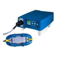
The purpose of this test is to check the leakage of current from the Warmer into saline. As IV uids are generally conductive, a uid warmer is considered to
be electrically connected to the patient similar to an ECG lead; therefore, the leakage needs to be tested. The setup for this procedure is described below.
Wire
Procedure
1. Leave the cap on the female end of the Disposable Cartridge.
2. Put an extension set on the male end.
3. Insert a piece of wire into the extension set tubing.
4. Fill the Disposable Cartridge and extension set tubing with saline. Note: It doesn’t matter which way the wire is inserted into the tubing, just be certain
that the wire is in contact with the uid.
5. Next, put a non-venting cap on the open end of the extension set.
6. Place the Disposable Cartridge setup in the Warmer.
7. Connect the ECG lead from the leakage tester to the wire inserted into the extension set tubing.
8. Perform the ECG lead leakage test.
Current Normal Single Fault
Earth leakage 5 mA 10 mA
Touch/chassis leakage 100 μA 500 μA
Patient leakage 100 μA 500 μA
From Table I. Leakage current limits (from IEC 60601-1)
Simulated use performance testing
A. enCheck Model 400
Equipment
enCheck (includes K type probe)
Thermal thermocouple meter with ± 5 °C accuracy
enFlow Controller (Model 121)
enFlow Warmer (Model 100)

 Loading...