Chapter 2: Installation and wiring
72 EST iO64 and iO500 Technical Reference Manual
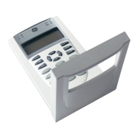
Printer wiring
RS-232 cable
DB-25 male
Printer
To RS-232 card
DB-25 serial port
on back of printer
LINE
FEED
FORM
FEED
TOP
SET
SELECT ALARM POWER PITCH MODE
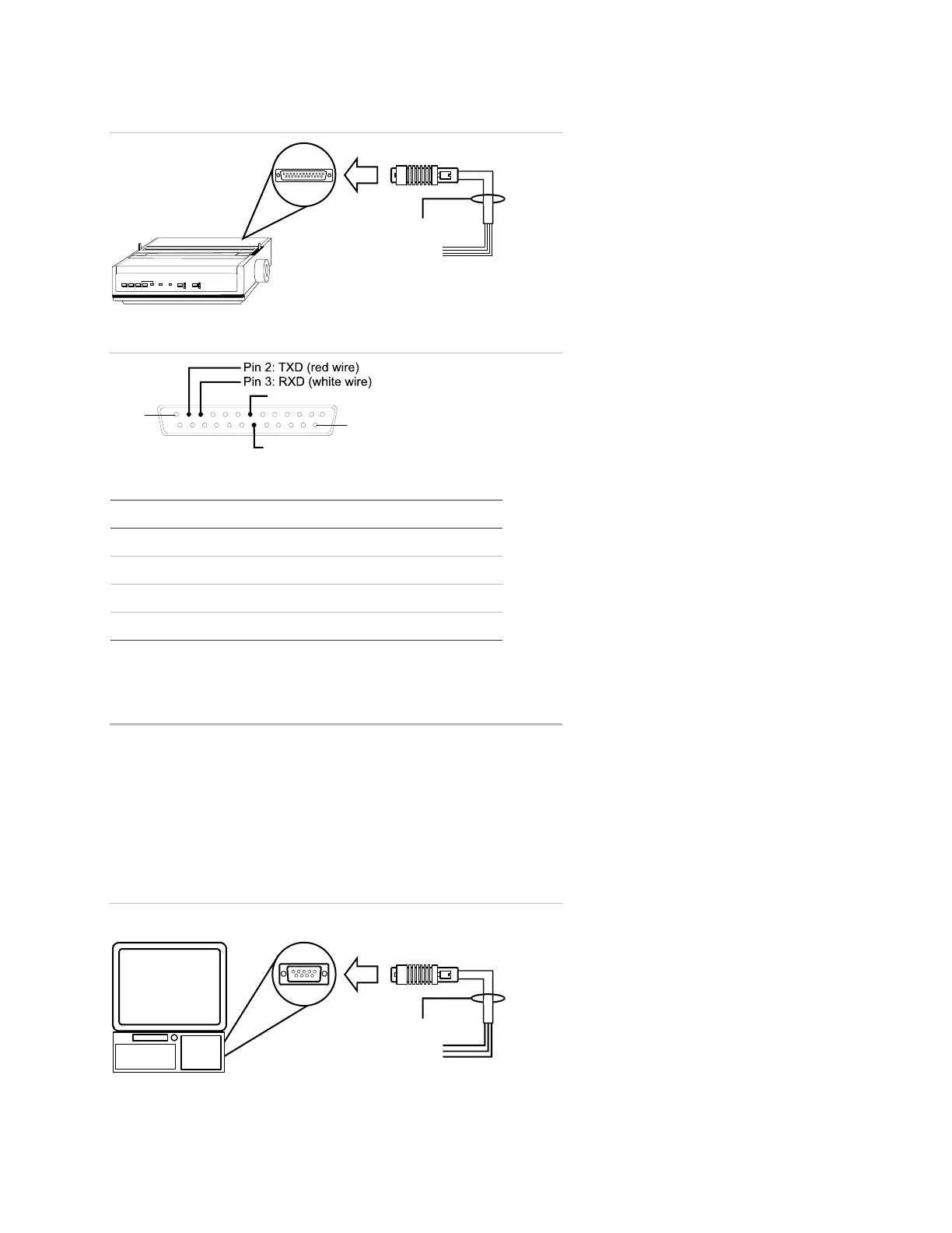
DB-25 pin connections
PIN 25
PIN 1
DB-25 male
(front view)
Pin 7: COM (black wire)
Pin 20: DTR (green wire)
SA-232 card to printer DB-25 connections
SA-232 card DB-25 Description
GND COM (pin 7) Black wire (ground connection)
RTS DTR (pin 20) Green wire (printer supervision)
TXD RXD (pin 3) White wire (communication)
RXD TXD (pin 2) Red wire (communication)
Computer download wiring
Wiring to a computer:
1. If you have a connected printer, disconnect it.
2. Locate a serial port (COM port) on the back of the computer.
3. Connect the DB-9 end of the RS-232 cable to the COM port on
the back of the computer.
4. Connect the other end of the RS-232 cable to the RS-232 card.
Computer download wiring
RS-232 cable
DB-9 female
Computer
DB-9
M port
on back of computer
To RS-232 card
 Loading...