Page 30 Chapter 4 — Theory of Operation
Chapter 4 — Theory of Operation
Overview
The Humilab Relative Humidity Generator uses a divided flow
method to accurately generate a selected relative humidity in a
large test chamber. The selected humidity is controlled using a GE
General Eastern Chilled Mirror Hygrometer System. This chapter
describes divided flow and the chilled mirror controller.
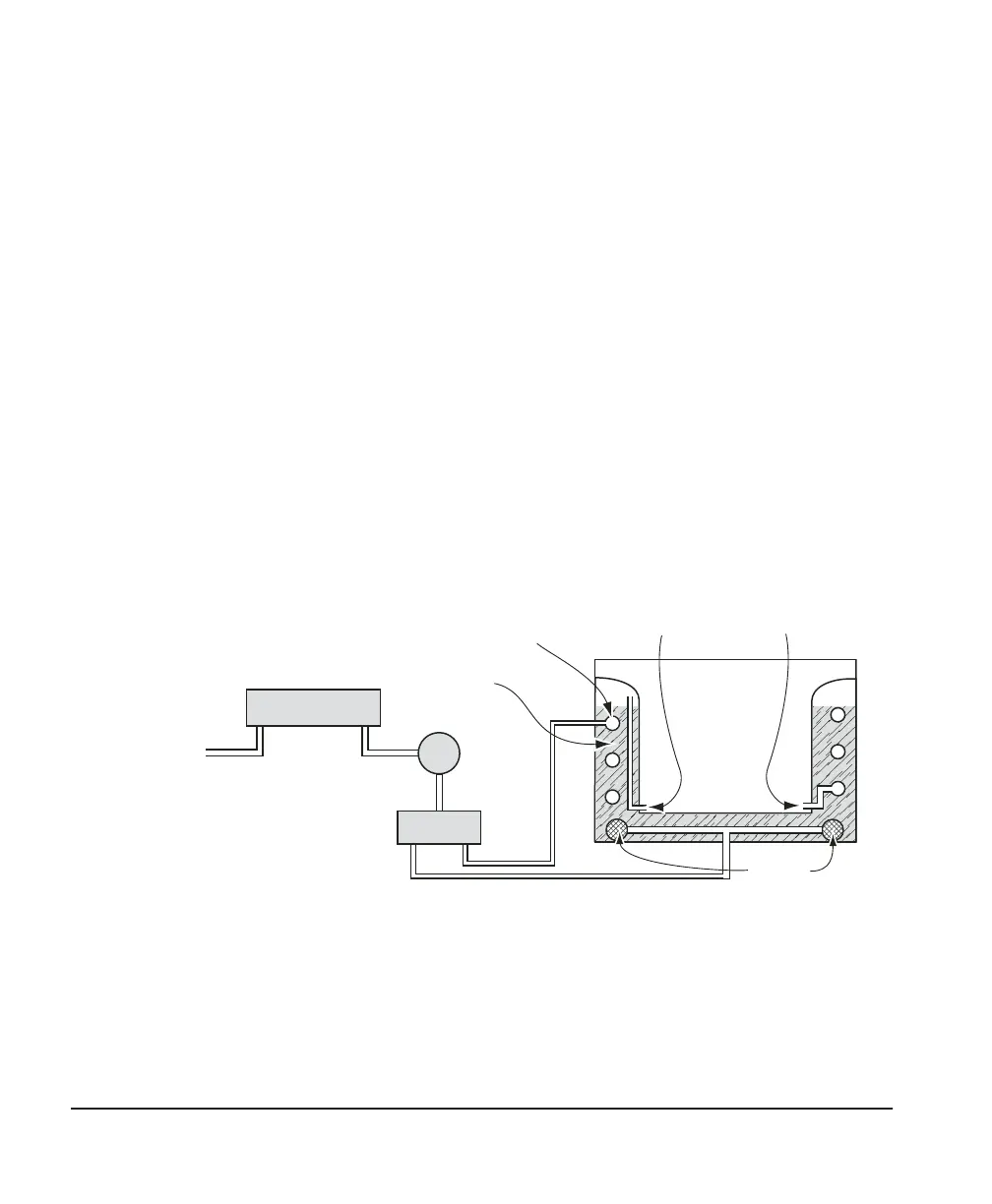
Divided flow
The Humilab’s chamber RH is controlled by time proportioning a
fraction of an air stream through a saturator and a desiccant. The
saturated air mixes with the dry air to produce the desired RH
value in the chamber. Figure 10 shows the basic block diagram of
the Humilab’s operation.
The operator selects the desired relative humidity on the front
panel, using the increment/decrement switch to scroll to the value.
The selected RH determines the duty cycle of a solenoid operated
wet air/dry air valve.
Desiccant
Cartridge
Solenoid
valve
Pum
p
-40°C DP
ir supply
(optional)
Tes t
chamber
Wet
gas
in
Dry
gas
in
Dry gas
temperature coil
(surrounding chamber)
Sparger
(bubbles air
through water)
Water jacket
Figure 10 — Basic Block Diagram