Page 8 Chapter 1 — Installation and Initial Setup
Electrical connections
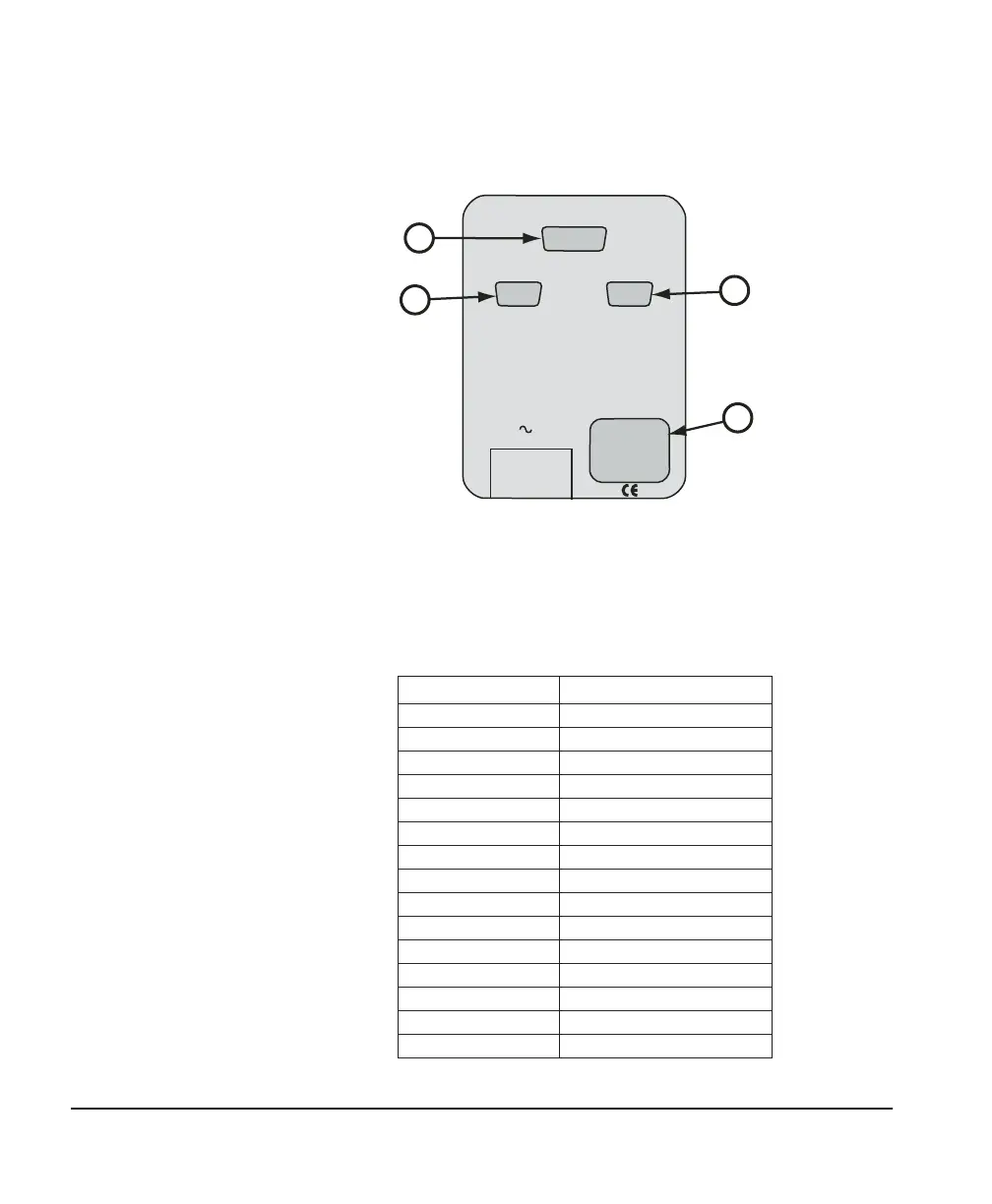
Electrical connections to the Humilab are made on the rear panel
as shown in Figure 3.
A. Analog outputs. Analog outputs are available to the operator via
the DB-15 connector located on the rear I/O panel. A cable suitable
for connecting to a terminal block is included. The connector
pinout is listed below.
DB-15 Pin No. Function
1 RH 4–20 mA (+)
2 RH 0–5 V (+)
3 Temp 4–20 mA (+)
4 N/C
5 Temp 0–5V (+)
6 Status
7 N/C
8 N/C
9 Service
10 Gnd (Rtn)
11 N/C
12 N/C
13 N/C
14 N/C
15 N/C
ANALOG OUTPUTS
REFERENCE RS-232 CONTROLLER RS-232
LINE
A
B
C
D
Figure 3 — Humilab electrical connection