iBox/iBox Kit
Installation and Maintenance Guide
GE Grid Solutions
994-0047-5.10-4 GE Information
CISPR 11-CE Mark Compliance
Important
For CISPR 11, Class A-CE Mark compliance on an iBox installed outside of a
protective enclosure, you must use ferrite clamps on the following:
• Serial communication cables attached to J2, J3, and J4
• Wiring connected to TB2-TB15 for digital inputs and control outputs
Note: Although the standalone iBox is CE Marked, GE does not guarantee the CE
Mark of third-party components of the iBox Kits (such as the 10/100BaseT Ethernet
Module or the AC and DC Analog Input Modules).
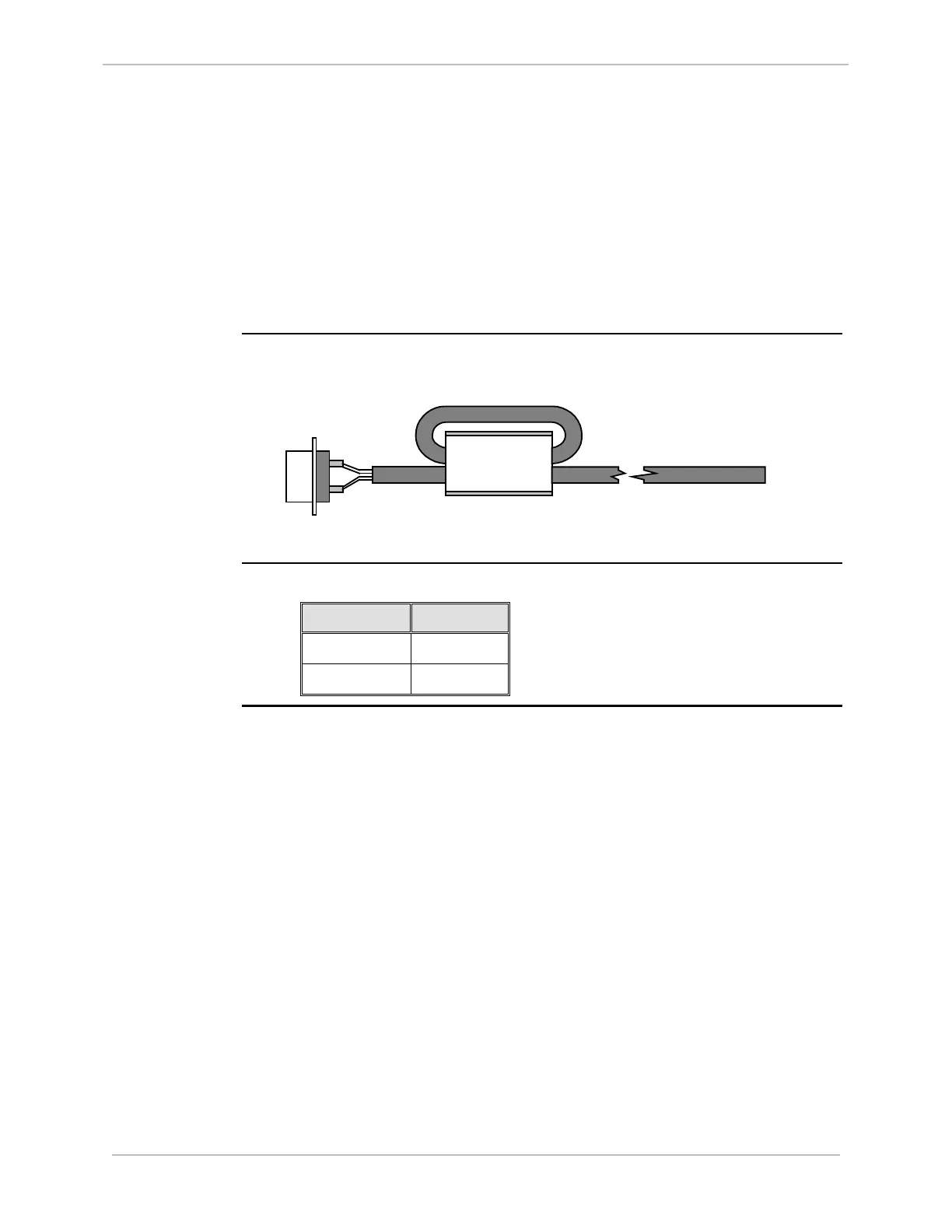
Ferrite Clamp
cabling/wiring
The following diagram illustrates the cabling/wiring loop through an installed ferrite
clamp.
Connection
Ferrite Clamp
Cable/Wiring
Part Numbers
Order the following part number for each of the external ferrite clamps you require.
Part Number Color
460-0031 White body
460-0049 Black body