GE Grid Solutions
iBox/iBox Kit
Installation and Maintenance Guide
GE Information
994-0047-5.10-4
Connecting Serial Interfaces, continued
Serial Port
Pinouts
The COM port pin-outs, for both RS-232 and RS-485 configurations, are as follows:
DB-9 Pin RS-232 RS-485
1 CD N/C
2 RX RX-
3 TX TX-
4 N/C N/C
5 Com GND Com GND
6 N/C* N/C
7 RTS TX+
8 CTS RX+
9 EARTH GND EARTH GND
* Radio Key Open Collector Output for COM Port 1 only (jumper selected with JP3
installed).
2-Wire RS-485
Cable
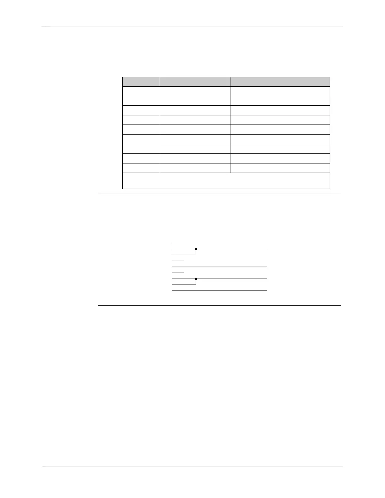
The following schematic shows the cable wiring necessary for 2-wire RS-485
operation.
Description PIN #
1
2
3
4
5
6
7
8
9
N/C
Data -
Data -
N/C
Common Ground
N/C
Data +
Data +
Earth Ground
- TX / RX
+ TX / RX
iBox Connectors J2, J3 or J4