EasyManuals Logo

GE iBox User Manual

GE iBox
172 pages
To Next Page IconTo Next Page
To Previous Page IconTo Previous Page
Page #78 background imageLoading...
Page #78 background image
iBox/iBox Kit
Installation and Maintenance Guide
GE Grid Solutions
78
994-0047-5.10-4 GE Information
What is an iBox Kit?, continued
Components
The iBox Kit consists of the following components:
iBox. See “What is an iBox?” on page 14 for more information.
24 VDC Power Supply (20 - 60 VDC or 88 - 300 VDC/88 - 264 VAC input)
10/100BaseT Ethernet Module (optional)
DC Analog Input Module (optional, eight DC analog inputs)
AC Analog Input Module (optional, 3 CT and 3 PT inputs)
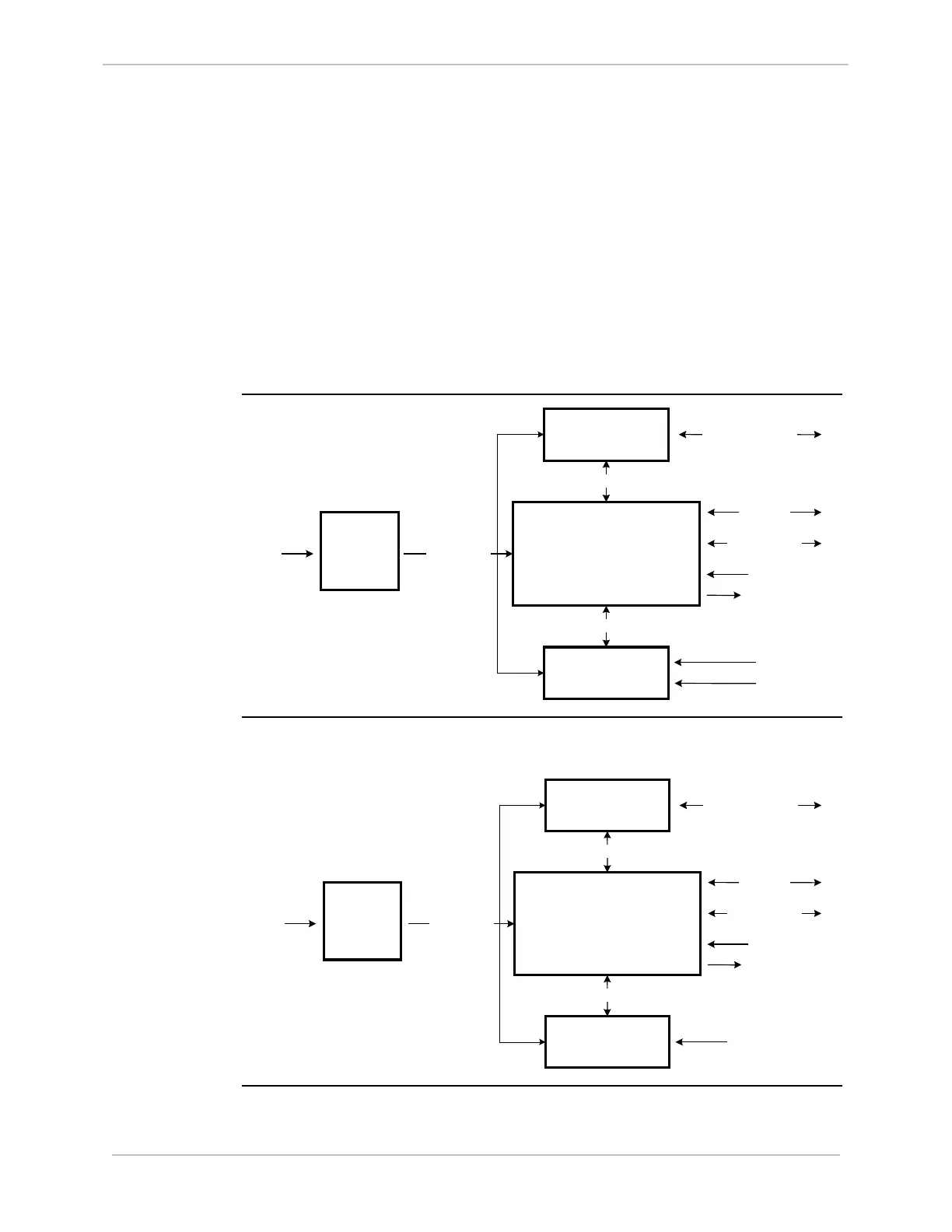
An example configuration of the iBox AC Kit is illustrated below (other options of
the iBox Kit are equipped differently):
AC Kit
Power
Supply
AC Analog Input
Module
iBOX
Ethernet Module
RS-485/PPP
10/100BaseT Ethernet
20 - 60 VDC
88 - 264 VAC
88 - 300 VDC
24 VDC Output
RS-485/Modbus
RS-232/485
Serial Port
RS-232
Maintenance Port
4 Digital Outputs
8 Digital Inputs
3 CT Inputs
3 PT Inputs
DC Kit
An example configuration of the iBox DC Kit is illustrated below (other options of
the iBox Kit are equipped differently):
Power
Supply
DC Analog Input
Module
iBOX
Ethernet Module
RS-485/PPP
10/100BaseT Ethernet
20 - 60 VDC
88 - 264 VAC
88 - 300 VDC
24 VDC Output
RS-485/Modbus
RS-232/485
Serial Port
RS-232
Maintenance Port
4 Digital Outputs
8 Digital Inputs
8 DC Analog Inputs

Table of Contents

Questions and Answers:

Question and Answer IconNeed help?

Do you have a question about the GE iBox and is the answer not in the manual?

GE iBox Specifications

General IconGeneral
BrandGE
ModeliBox
CategoryController
LanguageEnglish

Related product manuals