iBox/iBox Kit
Installation and Maintenance Guide
GE Grid Solutions
994-0047-5.10-4 GE Information
AC Analog
Inputs
(option)
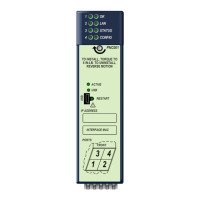
The iBox Kit provides the following AC Analog Inputs through an AC Analog Input
Module:
• Single circuit monitoring (wye connected)
• V
RMS
, I
RMS
, Phase Angle, Frequency, Power Factor
• Real Power (W), Reactive Power (VAR), Apparent Power (VA)
• Watt-Hour
• Nominal PT input range: 0 to 150 VLN or 250 VLL
• Nominal CT input: 5 A
• Frequency: 50/60 Hz
• Measurement range: 0 to 125% of nominal
• Accuracy: 0.3%
• Continuous overload withstand: 200% of nominal
• Short duration overload withstand: 100 A for 3 s
• Surge withstand as per IEEE C37.90.1, ANSI C62.41
• True RMS sampling at 64 samples per cycle
• Isolation: 2500 VAC/60 Hz
• Burden:
− Voltage & Current: 0.1 VA max
− Power Supply: 6 VA max
Power Supply
The power supply provides 24 VDC power to all iBox Kit components. It can also
deliver limited 24 VDC power to customer-provided equipment. The power supply
comes in two input voltage-range options:
• 20 - 60 VDC (7 A max)
• 88 - 300 VDC (1.4 A max) / 88 - 264 VAC (2.1 A max)
Maximum output is 24 VDC / 4 A or 24 VDC @ Vin min. For further clarification
regarding the power supply, consult the manufacturer’s power supply guide as listed
in the Additional Documentation section.
Remote
Maintenance
If your iBox Kit is equipped with an Ethernet interface, you can access and configure
the iBox from a remote PC running SGConfig.
 Loading...
