MA-001 – TRANSFIX-family Installation Manual – Rev 3.0 18-Jan-16 Page 31 of 55
10.3 Accessory Power
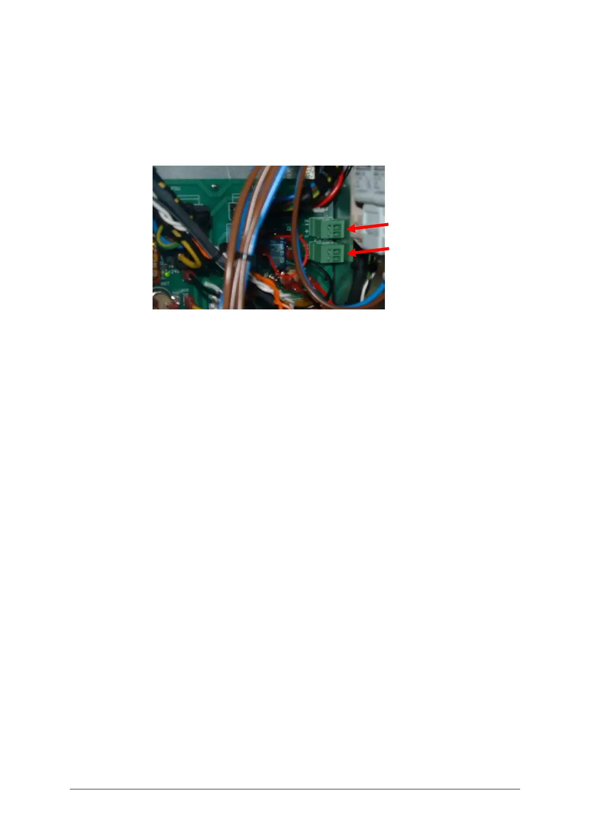
There are additional power points to connect +12 V DC or +24 V DC at 0.7 A accessories,
such as wireless modems or protocol converters. These are available on the AC board on
the back wall of the enclosure as shown in Figure 10—1.
Figure 10—1: Accessory power points for 12 V and 24 V
10.4 External Sensors
A transformer load sensor is provided in the product installation kit to measure and
record the transformer load. The transformer load sensor is a split core current sensor
that can be installed unobtrusively around a CT line receiving a feed from the main
bushing secondary wiring (usually located within the marshalling / control cabinet of the
transformer).
It should be possible to locate a suitable current transformer with a 0 A – 5 A secondary
circuit on which to mount the sensor. The sensor is supplied with 2.5 m (100 in.) of cable
and may be spliced to the required length to connect to the product with up to a total of
10 m (33 ft) of 20 AWG twisted pair cable. Longer cable lengths are possible depending
upon the quality of the cable. The load sensor connects to the bottom two terminals on
the left-hand side of the System board – terminals 33 and 34 (see Appendix I).

 Loading...


